


Chapter 7. PARAMETER SETUP
7-7
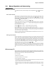
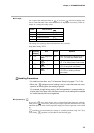
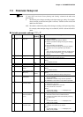
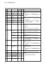
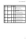
No. Item Code Item Factory User Setting
Setting Setting
1 L O C
0
2 P R T C
0
3 F L
0.0
4 P B 1
0U
5 S B 1 0U
6 O T L
0.0
7 1 O U T 0.0
(50.0)
8 R P 1 D
0
9 A T
0
10 S T
0
11 2 P 1 D 0
0: Key lock disabled
1: Display of setup data settings disabled
2: Display of parameter settings and program settings
disabled
3: Use of operation keys disabled
4: Display of parameter settings and program settings
displayed, and use of operation keys disabled
[Note]
Two or more key lock setting values for actual key lock
items and items assigned to can be displayed
and set.
0: Changing program settings enabled
1: Changing program settings disabled
0.0 to 120.0s
[Note]
0.0 disables the filter.
-1000 to 1000U
-1999 to 9999U
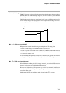
0.0 to 10.0% (0.1%s steps)
[Note]
0.0 disables the limit.
0.0 to 100%
[Note]
On heat/cool models, the factory setting is 50.0.
0: Automatic judgment of initialization is carried out by
advance operation.
1: Initialization is carried out by advance operation.
2: Initialization is not carried out by advance operation.
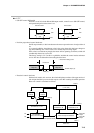
0: AT is disabled.
1: General AT is executed.
2: Overshoot-inhibited AT is executed.
3: AT by neural net is executed.
[Note]
On heat/cool models, “– – – –” is displayed, and
setting is not possible.
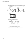
0: Smart-tuning is disabled.
1: The brake value is fixed to inhibit overshoot.
2: Overshoot is inhibited while automatically reviewing
the brake value.
[Note]
On heat/cool models, “– – – –” is displayed, and
setting is not possible.
0: 2 degrees of freedom PID is disabled.
1: 2 degrees of freedom PID is enabled.
[Note]
On heat/cool models, “– – – –” is displayed, and
setting is not possible.
PARA
Key lock
Program protect
Input 1 digital filter
Input 1 bias
SP1 bias
MV change limitter
(CH1)
PID operation initial
MV (CH1)
PID operation
initialization
Auto-tuning method
selection (CH1)
Smart-tuning
method selection
(CH1)
Advanced PID
selection (CH1)
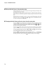
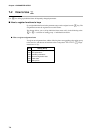
7-3 Parameter Setup List
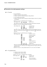
“U” and “%FS” used in the “Factory Setting” and “Setting” columns in the table mean
the following:
U: The decimal point changes according to the input range type setting. For example,
when one digit past the decimal point is allowed, -1999U becomes 199.9, and
9999U becomes 999.9.
%FS: The numbers and decimal point position changes according to the input range setting.
For example, when the input range is 0.0 to 800.0°C, 0%FS is 0.0 and 100%FS is
800.0.
■ Variable parameter settings “P A R A”
Note