


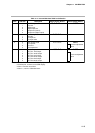
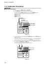
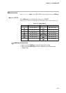
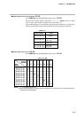
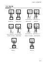
●Digital output test for control output (
00-04
)
Press PARA key until the PROG/SEG display shows (
00-04
).
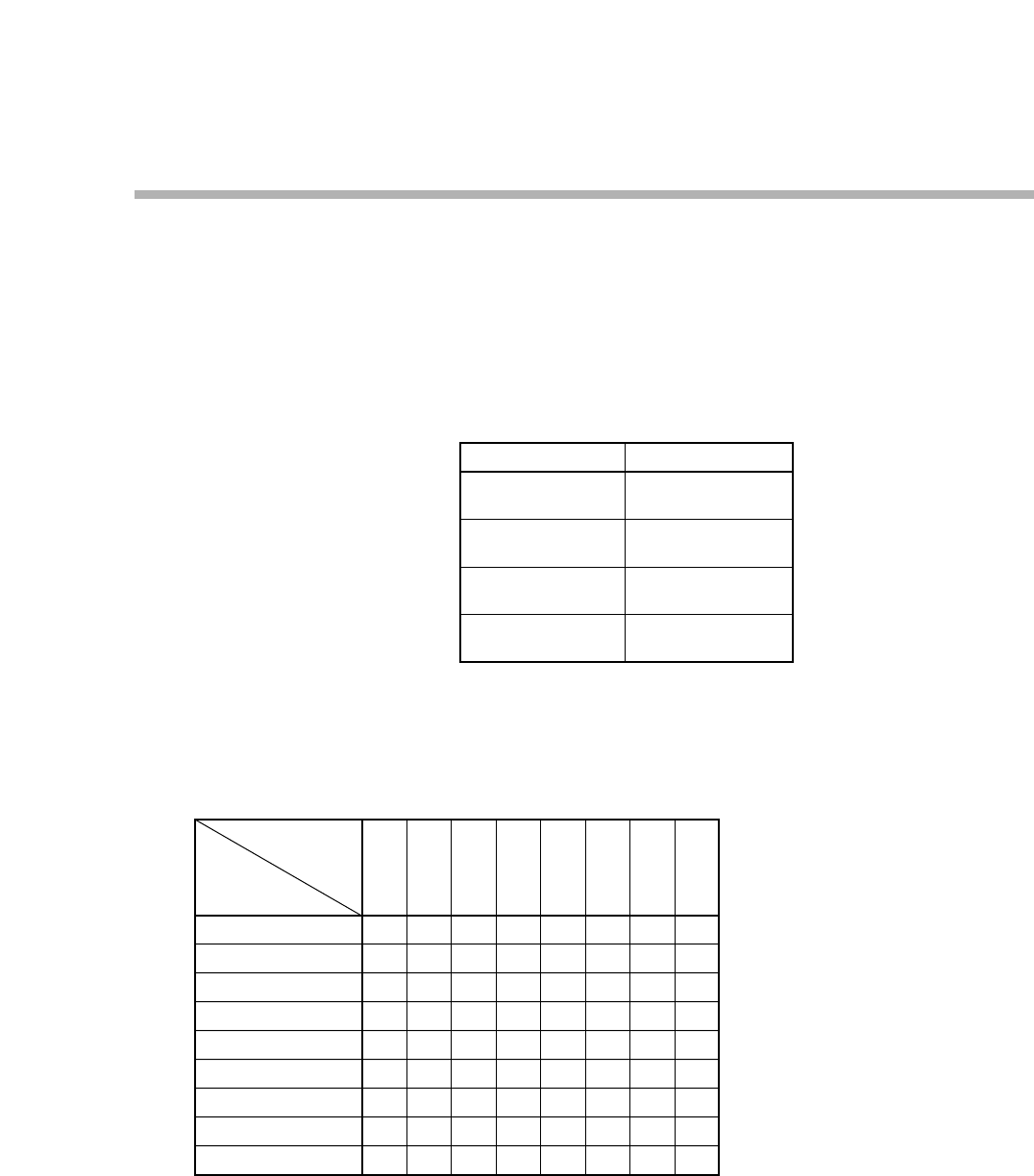
When the digit of upper display is changed by ↑, ↓, ←, or → keys, the state of voltage
pulse or relay control output is changed as shown in Table 11-5.
Since the 6D hardware is of voltage pulse output (0D and 2G hardware is of relay) spec-
ification, the ON/OFF check must be performed in meeting with the specification.
Table 11-5.
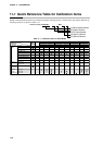
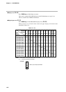
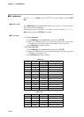
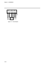
●Digital output test for event (
00-05
)
Press PARA key until the PROG/SEG display shows (
00-05
).
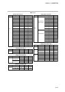
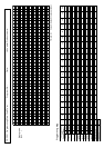
Table 11-6. DO
0.0.0.0.
0.0.0.1.
0.0.0.2.
0.0.0.4.
0.0.0.8.
0.0.1.0.
0.0.2.0.
0.0.4.0.
0.0.8.0.
—
ON
—
—
—
—
—
—
—
DO
Terminal
Number
Upper
Display
Notes: 1. “—” in the table means “OFF”.
2. Since the DO hardware is of open collector specification, the ON/OFF check must be performed in
meeting with the specification.
(4)
(5)
(6)
(7)
—
—
ON
—
—
—
—
—
—
(8)
(9)
—
—
—
ON
—
—
—
—
—
(49)
(55)
—
—
—
—
ON
—
—
—
—
(50)
(55)
—
—
—
—
—
ON
—
—
—
(51)
(55)
—
—
—
—
—
—
ON
—
—
(52)
(55)
—
—
—
—
—
—
—
ON
—
(53)
(55)
—
—
—
—
—
—
—
—
ON
↔
↔
↔
↔
↔
↔
↔
↔
0.0.0.0.
0.0.0.1.
0.0.0.2.
0.0.0.4.
Upper Display State
All OFF
6D, 0D, 2G output
CH1 ON
6D, 2G output
CH2 ON
6D output
CH3 ON
11-9
Chapter 11. CALIBRATION