


Chapter 6. OPERATION
6-1
Chapter 6. OPERATION
6-1 Turning the Power ON
The DCP301 is not equipped with a power switch or protective fuses. If necessary, prepare these externally.
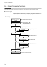
When a voltage of 90 to 264Vac is applied across terminals (1) and (2) on the DCP301, display appears for about 10s
after which control and other operations are started. During controller startup until start of operations, the LEDs on
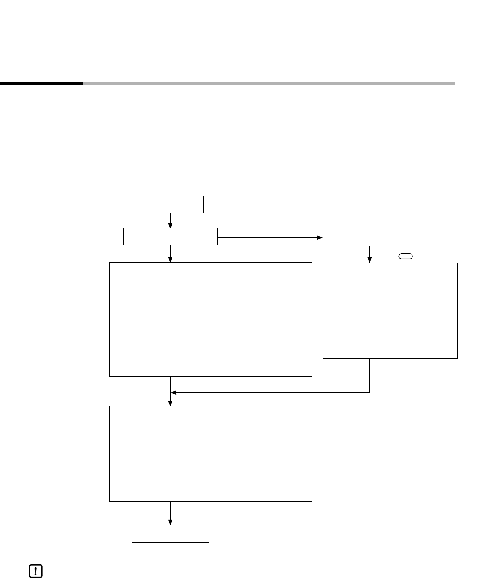
the profile display light successively at uneven intervals clockwise from top right. The following diagram shows the
flow of operations at startup.
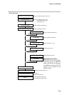
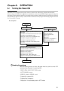
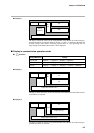
● Startup flow
Power ON
NO
YES
Start of operations
Check start of general reset
Press key.
RAM backup normal?
ENT
Continuation of program operation/constant-value oper-
ation modes
Continuation of READY/RUN/HOLD/FAST/END modes
Continuation of AUTO/MANUAL modes
(Continuation of manual value if in MANUAL mode)
Continuation of program No./segment No.
Continuation of segment progress time
Continuation of display No. of basic display state in
AUTO mode
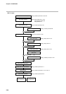
Parameter=factory shipment setting
Delete entire program.
Program operation mode
READY mode
AUTO mode
Program No.1=1/segment No.=1
Segment progress time=0
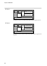
Cancellation of auto-tuning/smart-tuning
Cancellation of MFB automatic adjustment by 2G output
Initialization of G.Soak standby time
Initialization of PID operation
Initialization of event output state
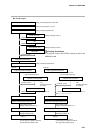
Setting display state → Basic display state
Display No. of basic display state in MANUAL mode
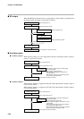
With the following modes and items, the state when the power is turned OFF
continues when the power is turned back ON.
• READY, RUN, HOLD, FAST, END modes
• AUTO, MANUAL modes
• MANUAL values in MANUAL mode
• Program No., segment No.
• Progress time in segment
• Display No. if in basic display state in AUTO mode
Handling Precautions