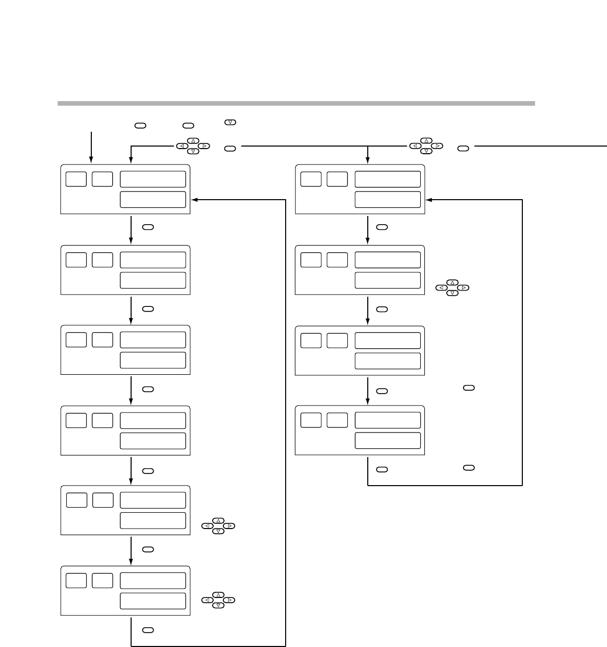
Chapter 11. CALIBRATION
Figure 11-1. Calibration Flowchart (1/2)
11-4
Notes: *; 1. This display shows the digits shown in the previous indication.
2. If wrong key operation is made when moving from one to another item, the display is returned
to the initial status of calibration mode. But, the mode is still in the calibration mode.
While pressing , press and simultaneously.
&
Function test
Key ON/OFF
Key ON/OFF
PROG SEG
0 0 0 1
Key test
Display test
PROG SEG
ON/OFF of display
ON/OFF of display
DI test
DI ON/OFF
Control output test
Relay Voltage pulse
Do output test
PV input
calibration item
1.0.1.1.
*
AdJS
Gain No. selection
00000
*
AdJS
Zero input count
After stabilized,
press .
Span input count
After stabilized,
press .
Input of Control
output ON/OFF
Input of DO
ON/OFF
0.0.0.0.
*
AdJS
PROG SEG
0 00 0
PROG SEG
0 0 0 3
PROG SEG
0 0 0 4
PROG SEG
0 0 0 5
PROG SEG
0 1 0 0
PROG SEG
0 1 0 1
PROG SEG
0 1 0 2
PROG SEG
0 0 0 3
Current input
count No.
Current count No.
stored
Current input
count No.
Current count No.
stored
ENTER
ENT
FUNC
&
ENTER
SETUP
SETUP
SETUP
SETUP
SETUP
SETUP
SETUP
SETUP
SETUP
SETUP
ENTER
ENTER


