


Chapter 5. FUNCTIONS
5-22
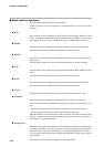
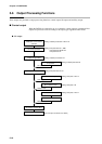
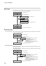
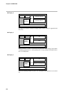
■ SP output
When the DCP301 is selected for use as a programmer, control output is operational. On
5G output models, SP output is processed is as follows.
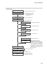
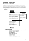
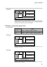
■ Auxiliary output
● Auxiliary output 1
When auxiliary output 1 or 2 are supported on 0D, 5G or 6D output models, auxiliary
output 1 is processed as follows.
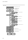
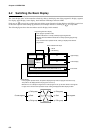
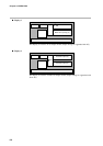
● Auxiliary output 2
When auxiliary output 2 is supported on 0D, 5G or 6D output models, auxiliary output 2
is processed as follows.
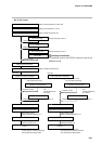
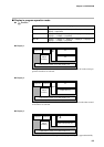
When auxiliary output 1 is supported on 2G, 3D or 5K output models, auxiliary output 2
is processed as follows.
MANUAL mode
Main output types
Upper/lower limit scaling
SP1 output
Output 1
READY mode
Upper/lower limit scaling
Manual SP1
MV in READY mode
Current output 4 to 20mA (0 to 20mA)
Setting: Setup data C 16
Setting: Setup data C 18
Setting: Setup data C 19/C20
Setting: Setup data C 19/C20
Auxiliary output 1 type
Upper/lower limit scaling
Output 2
4mA (0mA)
Current output 4 to 20mA (0 to 20mA)
When READY mode is entered at auxiliary output
type SP and deviation
When auxiliary output type is NOP
When auxiliary output type is set to MFB on non-
2G output models
When auxiliary output type is set to MV by program-
mer function on 5G output models
Setting: Setup data C46
Setting: Setup data C4 7 /C48
Auxiliary output 2 type
Upper/lower limit scaling
Output 3
4mA (0mA)
Current output 4 to 20mA (0 to 20mA)
When READY mode is entered at auxiliary output
type SP and deviation
When auxiliary output type is NOP
When auxiliary output type is set to MFB on non-2G
output models
When auxiliary output type is set to MV by program-
mer function on 5G output models
When auxiliary output type is set to MV by 3-position-
proportional control on 3D output models
Setting: Setup data C49
Setting: Setup data C50/C51