


4-2
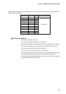
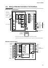
• Before wiring the DCP301, check the controller catalog No. and terminal Nos.
on the label on the rear of the body. After wiring the DCP301, be sure to check
the wiring for any mistakes.
• Maintain a distance of at least 50cm between I/O leads or communications
leads and the power lead. Also, do not pass these leads through the same
piping or wiring duct.
• When wiring with crimped terminals, take care to prevent contact with adjacent
terminals.
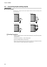
• When connecting the DCP301’s thermocouples in parallel to other controllers,
make sure that the total input impedance of the other controller is at least
1MΩ.
If the input impedance is less than 1MΩ, the DCP301 may not be able to detect
sensor disconnection.
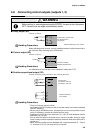
• When inputting the DCP301’s I/O (parallel connection in case of input) to an A/
D converter or analog scanner, read data may fluctuate.
To prevent this, adopt one of the following measures.
(1) Use a low-speed, integrating type A/D converter.
(2) Insert an isolator without a switching power supply between the DCP301
and A/D converter.
(3) Average data on a personal computer when reading data.
(4) If possible, set a filter for the input.
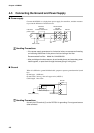
• Provide the wiring for the instrument power supply with a mains power shutoff
switch within reach of the instrument operator.
• Provide the wiring for the instrument power supply with a delayed operation
type (T) 1A current rating, 250V voltage rating fuse. (IEC 127)
• Devices and systems to be connected to this unit must have the basic insula-
tion sufficient to withstand the maximum operating voltage levels of the power
supply and input/output parts.
Handling Precautions