


Chapter 10. SPECIFICATIONS
10-1
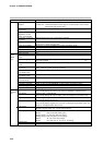
19
30 per program
RAMP-X system: Set by set points (SP) and time.
0 to 99h 59min, or 0 to 99min 59s (time unit selectable)
±0.01% (0.1s delay when segment time setting=0)
Set operating point.
Set ON and OFF times.
Set 0 to 8 (Set 0 for continuation of previous segment) (Set 0 to 4 on heat/cool models.)
Sets G.Soak width 0 to 1000U.
Sets program ON/OFF.
Sets program count 0 to 9999.
Sets program No.0 to 19 (0: no link)
Sets 8 alphanumerics for each program (not displayed on controller)
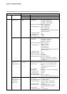
Thermocouple, resistance temperature detector, dc voltage, dc current multi-range
(See pages 2-8 and 2-9.)
±0.1%FS±1U (varies according to standard conditions, display value conversion and
range)
• At -100°C max. of K and T thermocouples: ±1°C1U
• At 260°C max. of B thermocouple: ±4%FS±1U
At 260 to 800°C: ±0.4%FS±1U
At 800 to 1800°C: ±0.2%FS±1U
• At 100°C max. of R and S thermocouples: ±0.2%FS±1U
At 100 to 1600°C: ±0.15%FS±1U
• At 300°C max. of PR40-20 thermocouple: ±2.5%FS±1U
At 300 to 800°C: ±1.5%FS±1U
At 800 to 1900°C: ±0.5%FS±1U
• Golden iron chromel thermocouple: ±1.5K±1U
• 2-digit range past decimal point by resistance thermometer detector input:
±0.15%±1U
• At 0 to 10mV range: ±0.15%FS±1U
• At -100°C max. of DIN U thermocouple: ±2°C±1U
At -100 to 0°C: ±1°C±1U
• At -100°C max. of DIN L thermocouple: ±1.5°C±1U
0.1s
Thermocouple, dc voltage input: ±1.3µA max. (at peak value, under standard conditions)
At 1V min. range: 3µA max.
dc current input: 50Ω ±10% (under operating conditions)
RTD input: 1.04mA ±0.02mA, current flow from terminal A (under operating conditions)
Changes in readout value at wiring resistance of 250Ω at both
ends are as follows by input conversion:
• 0 to 10mV, -10 to 10mV: Within 35µV
• 0 to 100mV: Within 60µV
• Other: Within 750µV
RTD input: ±0.01%FS max. in wiring resistance range 0 to 10Ω
Range of F01, F33, F38, P01, P33 and P38: ±0.02%FS/Ω max.
Allowable wiring resistance is 85Ω max. (including Zener barrier
resistance. When Zener barrier is used, this applies only to
ranges other than F01, F33, F38, P01, P33 and P38. Note that
site adjustment is required.)
Thermocouple disconnection detection allowable parallel resistance: 1MΩ min.
Thermocouple, dc voltage input: -5 to +15Vdc
dc current input: 50mAdc, 2.5Vdc
Upscale and downscale can be internally selected. (dc current input and dc voltage
input of 1V or more are only downscaled.)
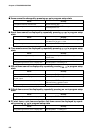
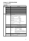
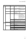
Item Specification
Program Number of programs
Number of segments
Segment setting system
Segment time
Basic time accuracy
Events (3)
Time events (5)
PID set No.
G.Soak
PV start
Cycle
Pattern link
Tag
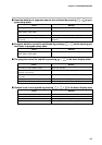
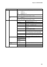
Input Input type
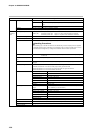
Input readout accuracy
Input sampling cycle
Input bias current
Input impedance
Measuring current
Influence of wiring resis-
tance
Allowable parallel resistance
Max. allowable input
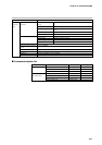
Burnout
Chapter 10. SPECIFICATIONS
10-1 Specifications
Thermocouple,
dc voltage input: