


Chapter 9. TROUBLESHOOTING
9-2
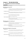
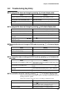
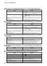
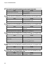
Alarm Code Alarm Name Description
A L 0 1 Input 1 over-range
A L 0 2 Input 1 under-range
A L 0 7 Input 1 RTD disconnection A
A L 0 8 Input 1 RTD disconnection B
A L 0 q Input 1 RTD disconnection C
A L 1 0 MFB disconnection
A L 1 1 MFB short-circuit
A L 1 2 MFB adjustment impossible
A L 7 0 A/D trouble
A L 8 1 Board configuration error
A L q 6 Program error
A L q 7 Parameter error
A L q 8 Adjustment value error
A L q q PROM error
■ Self-diagnostics only when certain functions are operating
● MFB (motor feedback) adjustment error
This error is detected when MFB automatic adjustment is not going smoothly on 2G
output models.
The corresponding alarm code is displayed when this error is detected.
To clear this alarm, either execute automatic adjustment again or turn the power OFF
then back ON again.
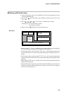
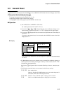
■ Alarm code display
When an input error or controller error is detected in the basic display state, the alarm
code and regular display are displayed alternately every second on the program No. and
segment No. displays. The table below shows alarm codes and alarm descriptions.
When two or more alarms occur at the same time, the alarm codes are displayed from the
smallest number upwards together with the regular display.
However, note that when setup data C 6 7 has been set to “1”, alarm codes are not dis-
played.
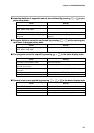
■ Alarm categories
PV range alarm groups: A L 0 1 to A L 1 2
Controller alarm groups: A L 8 1 to A L Q Q, and low battery voltage
(BAT LED on console blinks in case of low battery voltage.)
Remedy
Check input 1
Check line of RTD (resis-
tance temperature detector)
connected to input 1 for
disconnection, and terminal
connections.
Check MFB wiring.
Check wiring of MFB switch-
ing relay or motor specifica-
tions.
Ask for repair.
Ask for repair.
Check program setup, and
reset damaged data. *1
Check parameter setup, and
reset damaged data. *2
Ask for repair.
Ask for repair.
Input 1 has exceeded 110%FS
Input 1 has fallen below -10%FS
RTD line A is disconnected.
RTD line B or lines ABC are
disconnected.
RTD line C is disconnected.
MFB (Y, T, G) line(s) is
disconnected.
Y-G line or Y-T-G line is short-
circuited.
Faulty wiring, motor
incompatibility etc.
A/D converter has malfunctioned.
Faulty board configuration
Damaged program setup data
Damaged parameter setup data
Damaged analog input/output
adjustment data
Damaged system program
*1 A L q 6 goes out even if program setup data other the damaged data is reset.
*2
A L q 7 goes out even if parameter setup data other the damaged data is reset.