Chapter 7. PARAMETER SETUP
7-37
(5) Example: Using Yamatake Corporation’s PGM
VSSR : 3 to 6V
Z : 260Ω ± 5%
VD : 0.8 to 1.3V
• What value should I
O
be set to when connecting one PGM?
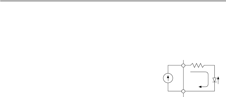
As shown in the figure on the right, a fixed-current system is used for the voltage
output of this controller. The fixed current can be calculated as follows from the
input voltage range of PGM.
8.9mA ≤ 1 ≤ 17.2mA
IMIN x ZMIN + VD/MIN > 3
IMIN > 8.9mA
IMAX x ZMAX + VD/MAX < 6
IMAX < 17.2mA
• How many PGMs can be connected?
A current of 8.9mA or more must flow to a single PGM. On the other hand, the
maximum current of the controller is 22.0mA. Accordingly, two PGMs can be con-
nected in parallel.
In the case of a series connection, due to the maximum output current (22.0mA)
and allowable load resistance (600Ω), the maximum voltage that can be applied to
a load becomes 13.2V (22.0mA x 600Ω).
When a current of 8.9mA flows to a PGM, the maximum voltage at both of its input
terminals becomes 3.7V.
0.0089 x 260 x 1.05 + 1.3 = 3.7V
Accordingly, 13.2 ÷ 3.7 = 3.56, which means that three PGMs can be connected in
series.
The above calculation assumes operation in the worst conditions. For example,
even if four PGMs are connected in series, they should operate normally if a volt-
age of 3V or more is applied to each of the PGMs in a voltage ON state.
● C q 0 (Special functions)
• Normally set to 0.
• In the case of setup 102, current output (including heat-cool output) 0 to 100% for the
control output becomes 0 to 20mA. Note, however, that at 0% or less, the current is
0mA.
At output 1mA or less, accuracy is ±0.5%.
• In the case of setup 103, current output (including heat-cool output) and auxiliary out-
put 0 to 100% for the control output becomes 0 to 20mA. Note, however, that at 0% or
less, the current is 0mA.
At output 1mA or less, accuracy is ±0.5%.
• When the input 1 range type (C 0 3) is an RTD in setup 241, Zener barrier adjustment
(C 9 1) is displayed.
Z
I
PGMDCP301
V
D


