


Chapter 4. WIRING
4-19
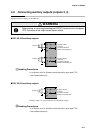
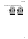
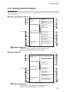
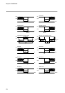
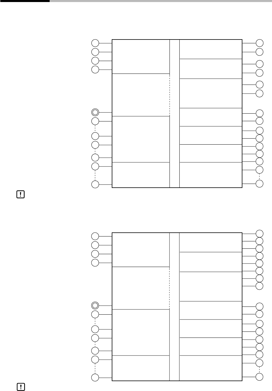
4-14 Isolating Inputs and Outputs
The following figures show isolation between inputs and outputs. Solid lines show isolated items, and dotted lines
show non-isolated items.
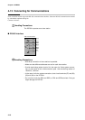
■ Control outputs 0D, 5G, 6D, 3D, 5K
31
11
12
14
15
17
18
4
5
6
7
8
9
10
49
56
32
33
34
21
25
41
48
57
61
Input 1
(full multiple-input PV
supported)
Output 1
(relay, current, voltage output)
Output 2
(relay, current, voltage output,
auxiliary output)
Output 3
(auxiliary output)
Event output 1
(relay output 1a)
Event output 2
(relay output 1a)
Event output 3
(relay output 1a1b)
Time event outputs 1 to 5
(open-collector output)
Loader communications
I/O
Loader jack
12 external switch inputs
Communications I/O
(RS-485)
Digital circuit
31
11
12
13
14
15
16
17
18
4
5
6
7
8
9
10
49
56
32
33
34
21
25
41
48
57
61
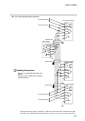
Input 1
(full multiple-input PV
supported)
Output 1
(control output 1a relay x 2)
Motor feedback input
Output 3
(auxiliary output)
Event output 1
(relay output 1a)
Event output 2
(relay output 1a)
Event output 3
(relay output 1a1b)
Time event outputs 1 to 5
(open-collector output)
Loader communications
I/O
Loader jack
12 external switch inputs
Communications I/O
(RS-485)
Digital circuit
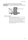
The loader jack is not isolated from internal digital circuits.
Be sure to cap the loader jack when it is not in use.
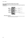
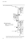
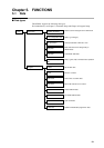
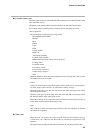
■ Control output 2G
Handling Precautions
Handling Precautions
The loader jack is not isolated from internal digital circuits.
Be sure to cap the loader jack when it is not in use.