


Chapter 4. WIRING
4-7
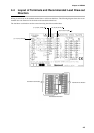
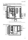
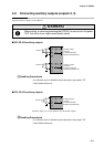
* On 2G, 3D or 5K models, (17) and (18) are the auxiliary outputs.
On 0D, 5G or 6D models, (14) and (15), and (17) and (18) are the auxiliary outputs.
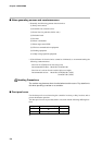
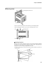
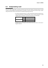
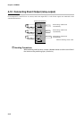
4-6 Wiring of Standard and Add-on Terminal Base
■ Standard terminal layout
■ Add-on terminal layout
10
8
9
6
7
4
5
3
1
2
20
18
19
16
17
14
15
13
11
12
24
25
23
21
22
33
34
31
32
29
30
28
26
27
RSW1
RSW2
RSW3
RSW4
*
mAdc
COM
V, mV
1
3
Y
EV1
EV2
EV3
T
G
2
90 to 264Vac
50/60Hz
Instrument
power supply
FG (Frame GND)
Event outputs
2G output
OD output
3D output
5G output
6D output
5K output
Auxiliary output
Relay
Relay
4 to 20mA
voltage
4 to 20mA
voltage
4 to 20mA
Output 1
Output 2
Auxiliary
output 1
Auxiliary
output 2
External switch input (RSW)
Current
input
Input
Resistance
temperature
detector
Voltage input
Thermocouple
input
Auxiliary output
4 to 20mA
Recorder, etc.
44
45
46
47
48
43
41
42
55
56
53
54
51
52
49
50
63
64
62
59
60
57
58
61
RSW5
T1
T2
T3
T4
T5
SDA
SDB
RDA
RDB
SG
RSW6
RSW7
RSW8
RSW9
RSW10
RSW11
RSW12
External switch
inputs
To terminals
Time event outputs
Load
Load
Load
Load
Load
External
10 to 29Vdc power supply
Bias circuit
RS-485
communications
25