


Chapter 8. PROGRAM SETUP
8-5
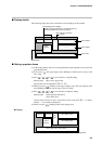
SP
TM
– –– –
– –– –
: LED lit
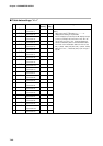
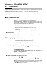
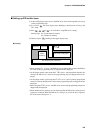
Program/Segment No. Display
Basic indicator LED lamps
Program No. Segment No.
Pattern
tendency
Upper display
Lower display
Event LEDs
EV1 to EV3 and T1 to T5 all out
Profile Display
Displays program/segment No. currently being set up.
Decimal point blinks in program setup state.
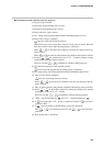
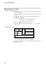
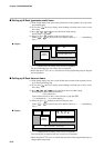
■ Setting up pattern items
(1) In the setting display state, move to the pattern item of the segment to be set up on the
programming map.
(2) If you press
ENT
, the upper display starts blinking to indicate start of entry to the
No.1 setup.
(3) Press , , or to set to the No.1 setup SP setting.
Setting range: SP1 lower to upper limit
(Set the SP1 limit in setup data C 0 Q or C 1 0.)
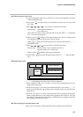
(4) When you press
ENT
, blinking on the upper display stops. The lower display then
starts blinking to indicate start of entry to the No.2 setup.
(5) Press , , or to set to the No.2 setup time setting.
Setting range: 0:00 to 99:59 (h:min/min:s)
0.0 to 599.9 (0.1s)
(Select either of h:min or min:s as the time unit in setup data C 6 4. “:” is substi-
tuted by “.” as it cannot be displayed.)
(6) When you press
ENT
, blinking on the lower display stops.
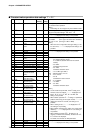
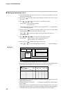
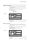
● Display
SP
TM
SP1 setting value
Time setting value
Program No. Segment No.
Pattern
tendency
EV1 to EV3 and T1 to T5 all out
“- - - -” is displayed for the SP and time setting values in non-set segments.
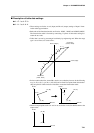
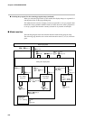
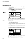
■ Display details
The following figure shows the conventions used for displays in this manual.