


Chapter 9. TROUBLESHOOTING
9-12
Connector
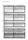
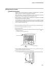
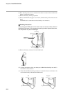
(6) Place the body on its save on a desk or flat surface so that the side on which the
battery is installed is facing up.
(7) Remove the battery from its gray holder.
(8) Remove the RAM board (approx. 3cm x 8cm) with the battery still connected to the
board.
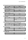
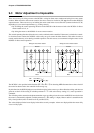
The RAM board is connected to the base board by two connectors.
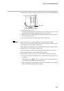
When placing the RAM board on the desk, make sure that the solder surface of
the board is face down. If the component mounting surface is placed face down,
the components may become damaged.
Connector
Connector
RAM board
(approx. 3cm x 8cm)
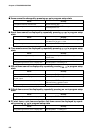
(9) Remove the battery connector from the RAM board.
(
10
) Connect the connector of the new battery to the RAM board making sure that it is
inserted the correct direction.
(
11
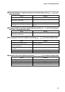
) Mount the RAM Board making sure that it is mounted in the correct direction. Do
not insert the battery cable under the RAM board.
OK No good
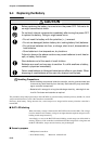
Handling Precautions