


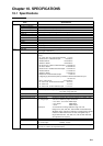
Chapter 10. SPECIFICATIONS
10-2
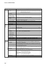
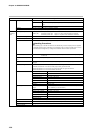
Over-range detection
threshold
Cold junction compensa-
tion accuracy
Influence of surrounding
temperature on cold
junction compensation
Cold junction compensa-
tion system
Scaling
Square root extraction
Linearization table approximation
Input bias
Digital filter
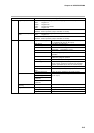
Number of inputs
Types of connectable
outputs
Terminal voltage (open)
Terminal current (short-
circuit)
Allowable contact resistance
(dry contact)
Residual current (allowable
open-collector ON)
Leakage current (allowable
open-collector OFF)
Parallel connection to
other instruments
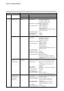
Assignments (fixed)
Assignments (variable)
Input sampling cycle
ON detection min. hold time
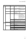
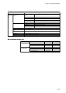
Upper display
Lower display
Program No. display
Segment No. display
Profile display
Status displays
Operation keys
Loader connector port
Input
External
Switch
(RSW)
Input
Indication
/Program-
mer
110%FS min.: Upscaled
-10%FS max.: Downscaled (Note that F50 range is not downscaled. Lower readout
limit of B18 range is 20°C, 68°F.)
±0.5°C (under standard conditions)
±0.2°C (at 0 to 50°C range)
Internal/external (0°C only) compensation selectable
-1999 to 9999U (settable at dc voltage and dc current ranges. Reverse scaling and
decimal point repositioning possible)
Dropout 0.1 to 10.0%, Possible by dc current and voltage ranges
12 (both line ends fixed, 11 points variable)
-1000 to 1000U variable
0.0 to 120.0s variable (filter OFF at 0.0)
12
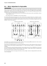
Dry contacts (relay contact) and open-collector (current sink to ground)
10.4 to 12.6V (under operating conditions) across common terminal (terminal 25 ) and
each input terminal
5.0 to 6.6mA across each terminal (under operating conditions)
ON: 700Ω max. (under operating conditions)
OFF: 10kΩ min. (under operating conditions)
3V max. (under operating conditions)
0.1mA max. (under operating conditions)
Can be connected to DCP301/302 series.
RUN, HOLD, RESET, ADV, program No.
FAST, PV start, AT, AUTO/MANUAL, G.Soak cancel, reverse/direct action
0.1s
0.2s (program No. 0.4s)
Green 4-digit, 7-segment LED
This normally displays PV values. Item codes are displayed in parameter setup.
Orange 4-digit, 7-segment LED
This normally displays SP values. Setting values are displayed in parameter setup.
Green 2-digit, 7-segment LED
This normally displays program No.
Green 2-digit, 7-segment LED
This normally displays segment No. Item Nos. are displayed in parameter setup, and
alarm No. is displayed when alarm occurs.
6 orange LEDs
Displays program pattern rise, soak and fall tendencies.
22 round LEDs
Modes: RUN, HLD, MAN, PRG (green)
Display details: PV, SP, OUT, TM, CYC (green)
Battery voltage: BAT (red) (blinks at low voltage)
Status: AT, OT1, OT2, OT3 (orange)
Events: EV1, EV2, EV3, T1, T2, T3, T4, T5 (orange)
13 rubber keys
1 (dedicated cable with stereo miniplugs)
Item Specification