


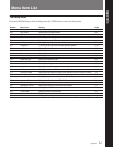
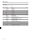
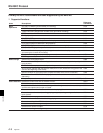
Menu Item List
Appendix
A-6 Appendix
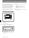
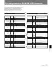
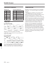
Connection of connectors
MD deck side Personal computer side
Pin No.
Signal Signal Description
2 RxDATA N TxDATA Transmit Data
3 TxDATA n RxDATA Receive Data
4 DTR n DSR Data Set Ready
5 GND — GND Signal Ground
6 DSR N DTR Data Terminal Ready
7 RTS n CTS Clear To Send
8 CTS N RTS Request To Send
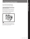
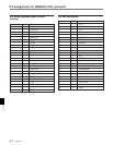
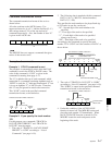
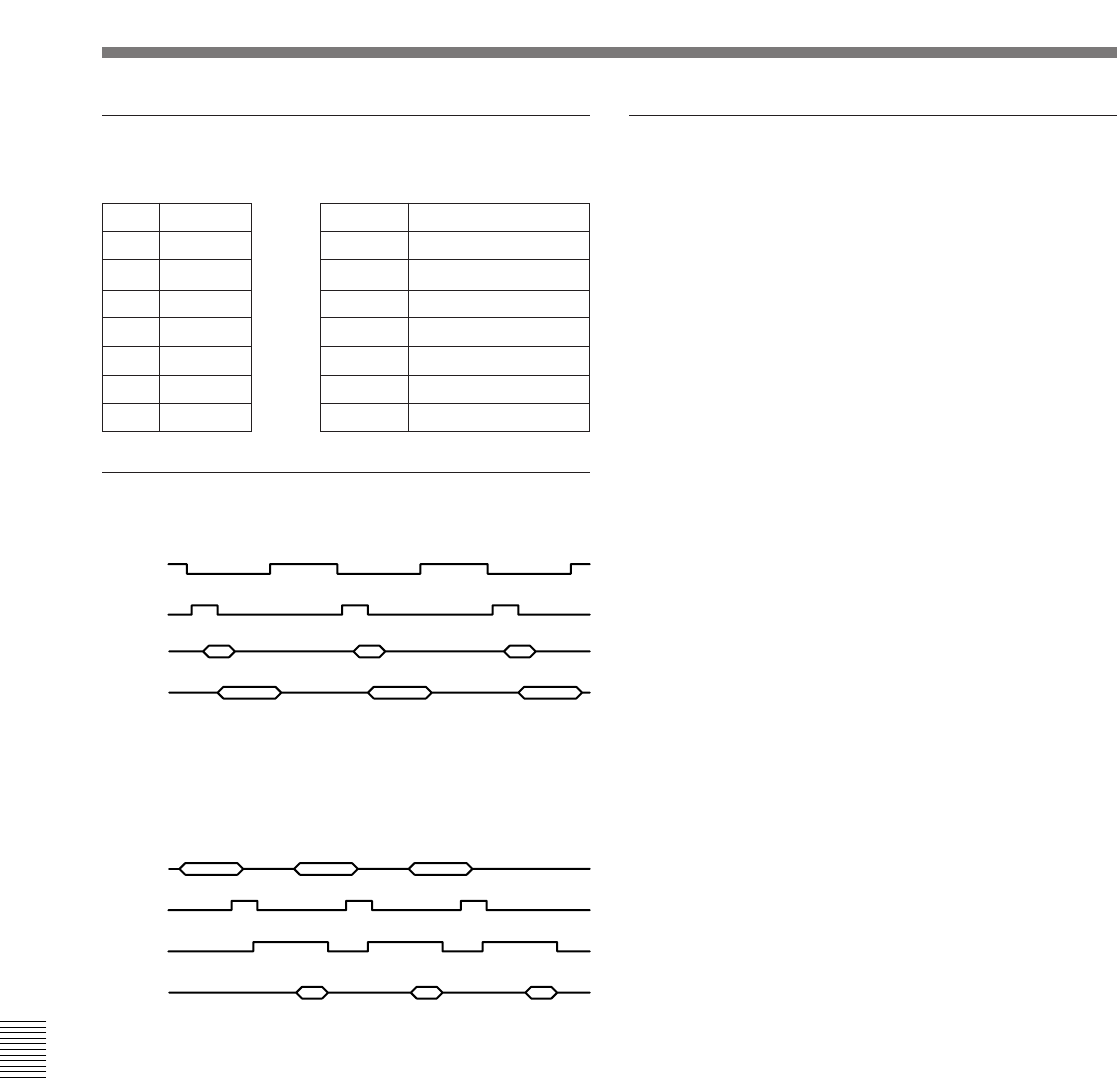
Timing chart
In transmitting data
CTS
TxRDY
WRITE
TxDATA
When the CTS becomes enabled, the TxRDY
(TxREADY) signal of the deck rises up and the deck
returns 1 byte of data.
In receiving data
RxDATA
RxRDY
RTS
READ
Upon reception of data, the RxRDY (RxREADY)
signal of the MDS-B5 rises up and the set disables the
RTS to read that data, then it enables the RTS again.
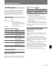
Transmission rate
The deck can use the transmission rate of maximum
9,600 bauds. As for practical figures at the SMPTE
29.97 Hz:
9600 (bit/sec)/11 (bit)/29.97 (1/sec)=29.12 (byte)
1 (sec)/9600 (bit/sec)*11 (bit)=1.145 (msec)
Namely, in one frame, the maximum number of bytes
is 29 and its byte interval is 1.145 msec. Upon
reception of a command in one cycle, the set uses the
RTS/CTS of hardware handshake to deassert that RTS
(0) line so that it does not receive the next command
block for subsequent 30 msec. This means that if the
command blocks are transmitted at random, the
contents of transmission accumulate or they are
destroyed. Also, since the data is received by the
interrupt processing of CPU, the communication
ignoring handshake, transfer clock or transmission rate
allows the set to receive data precedently, causing
other processing not to be executed and resulting in
stop of operation. (The deck will be recovered if data
reception is canceled.) Thus, the above points should
be taken into consideration when making a software
using this interface.
RS-232C Protocol