


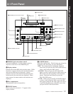


2-1 Front Panel
Chapter 2 Function of Parts and Controls
2-4 Chapter 2 Function of Parts and Controls
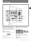
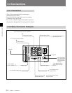
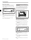
6 Ground connector
Connects directly to ground.
7 AC IN connector
Connects to an AC outlet with the supplied AC power
cord.
8 IEC(958) IN/OUT connector (RCA-type, phono)
Inputs digital audio signals for professional use
(IEC958-TYPE1) or consumer use (IEC958-TYPE2).
Outputs digital audio signals for consumer use
(IEC958-TYPE2).
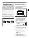
9 PLAYBACK/RECORD level controls and
MODE switch
Adjust the analog input and output reference level
during recording or playback. Adjust the level of each
channel (CH-1(L)/CH-2(R)) by turning the control
with a flat screwdriver.
MODE switch
Selects monaural or stereo mode for the analog input/
output signal.
When MONO is selected during playback, the signals
of channel 1 and 2 are mixed and lowered to below –6
dB, then output from ANALOG OUT CH-1(L) and
CH-2(R).
When MONO is selected during recording, the signals
from ANALOG IN CH-1(L) and ANALOG IN CH-
2(R) are mixed and lowered to below –6 dB, then
recorded from both channels. The MODE switch just
mixes the input and output signals and has nothing to
do with the monoaural recording mode based on the
MiniDisc format.
For the monoaural recording mode, see “To record in
monoaural mode” on page 4-2.
Note
If a signal is recorded from only one ANALOG IN
connector in monaural mode, the recording level will
be –6 dB lower than that recorded in stereo mode. In
this case, use the PLAYBACK/RECORD level control
to bring the recording level up to that of stereo mode.
0 RS-232C connector
15
69
You can use a personal computer connected to the
MDS-B5’s RS-232C connector to control the MDS-B5
including following operations:
• Button operations
PLAY/PAUSE, STOP, REC, EJECT, PREVIOUS,
NEXT, CUE STDBY
• Direct track access
• Selecting menu functions
Selecting the timing for the end-of-message (EOM)
tally signal output, setting the AUTO PAUSE and
AUTO CUE functions, setting the LevelSync
function, and selecting the input signal
• Displaying time and character data and messages on
an external computer
See “RS-232C Protocol” on page A-5 for details.
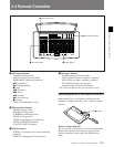
!¡ REMOTE connector
Connects the supplied remote controller.
2-2 Rear Panel