


Chapter 1 Components
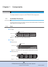
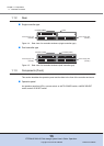
1.1 Controller Enclosure
ETERNUS DX60 S2 Disk storage system User’s Guide -Operation-
19
Copyright 2012 FUJITSU LIMITED P3AM-5512-03ENZ0
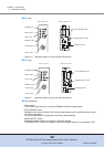
■ iSCSI model
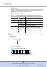
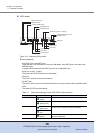
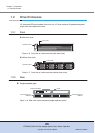
Figure 1.13 Controller (iSCSI model)
● Part explanation
• LAN (RMT) port, LAN (MNT) port
These are the RJ-45 connectors to connect LAN cables. LAN (RMT) port is not used in the
EMEA&I region.
A single controller has one LAN (RMT) port and one LAN (MNT) port.
• iSCSI port (0 (left), 1 (right))
These ports are RJ45 connectors for LAN cables.
• PWC port
This port is used for power synchronization.
• DI (OUT) port
This port is used to connect a controller enclosure to a drive enclosure with a miniSAS cable.
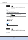
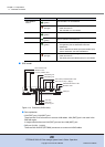
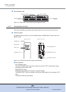
• LEDs
The states of LEDs are listed below.
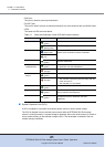
Table 1.5 Status and meanings of each LED (iSCSI model controller)
LED name LED status Controller status
SCU STATUS
(green)
The SCU is in normal status.
(blinks green)
SCU is charging.
IDENTIFY
(blinks blue)
As ordered via ETERNUS Web GUI, the installation
location of the controller enclosure is identified.
(off)
DI (OUT) LINKUP
(green)
The link between the DI (OUT) port and the destination
has been established.
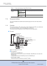
DI (OUT) port
PWC port
MASTER LED
ACT LED
LINK LED
UNIT READY/FAULT LED
iSCSI port (0 (Left), 1 (Right))
FAULT LED
LINK LED
LAN (RMT) port
DI (OUT) LINKUP LED
SCU STATUS LED
IDENTIFY LED
LAN (MNT) port