


ETERNUS DX60 S2 Disk storage system User’s Guide -Operation-
10
Copyright 2012 FUJITSU LIMITED P3AM-5512-03ENZ0
List of Figures
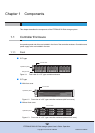
Figure 1.1 Front view of a 2.5" type controller enclosure............................................................................ 12
Figure 1.2 Front view of a 3.5" type controller enclosure (with front cover)................................................ 12
Figure 1.3 Front view of a 3.5" type controller enclosure (without front cover)........................................... 12
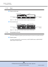
Figure 1.4 Rear view of a controller enclosure (single controller type)....................................................... 13
Figure 1.5 Rear view of a controller enclosure (dual controller type) ......................................................... 13
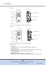
Figure 1.6 Operation panel (2.5" type controller enclosure) ....................................................................... 14
Figure 1.7 Operation panel (3.5" type controller enclosure) ....................................................................... 14
Figure 1.8 2.5" type disk ............................................................................................................................. 15
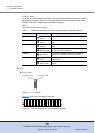
Figure 1.9 Disk slot numbers (2.5" type controller enclosure) .................................................................... 15
Figure 1.10 3.5" type disk ............................................................................................................................. 16
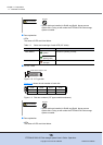
Figure 1.11 Disk slot numbers (3.5" type controller enclosure) .................................................................... 16
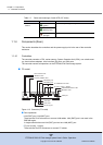
Figure 1.12 Controller (FC model) ................................................................................................................ 17
Figure 1.13 Controller (iSCSI model)............................................................................................................ 19
Figure 1.14 Controller (SAS model).............................................................................................................. 20
Figure 1.15 Power supply unit ...................................................................................................................... 22
Figure 1.16 Front view of a drive enclosure (with front cover)...................................................................... 23
Figure 1.17 Front view of a drive enclosure (without front cover)................................................................. 23
Figure 1.18 Rear view of drive enclosure (single expander model).............................................................. 23
Figure 1.19 Rear view of drive enclosure (dual expander model) ................................................................ 24
Figure 1.20 LEDs on the front side of the drive enclosure............................................................................ 24
Figure 1.21 3.5" disk ..................................................................................................................................... 25
Figure 1.22 Disk slot numbers (drive enclosure) .......................................................................................... 25
Figure 1.23 Expander ................................................................................................................................... 26
Figure 1.24 Power supply units .................................................................................................................... 27
Figure 1.25 Power distribution unit (1U) ....................................................................................................... 28
Figure 1.26 Power Distribution Units (2U, Max 6 enclosures connection).................................................... 29
Figure 1.27 Power Distribution Units (2U, Max 8 enclosures connection).................................................... 29
Figure 2.1 ON position (marked "|") of the main line switches on a 1U power distribution unit .................. 30
Figure 2.2 ON position (marked "|") of the main line switches on a 2U power distribution unit .................. 31
Figure 2.3 OFF position (marked "O") of the main line switches on a 1U power distribution unit .............. 31
Figure 2.4 OFF position (marked "O") of the main line switches on a 2U power distribution unit .............. 32
Figure 4.1 LAN control (switching of the Master CM) ................................................................................. 50
Figure 4.2 LAN control (when the IP address of the Slave CM is set)........................................................ 51
Figure 4.3 ETERNUS Web GUI screen...................................................................................................... 52
Figure 4.4 Event notification ....................................................................................................................... 54
Figure 5.1 Position of 2.5" disk slots........................................................................................................... 56
Figure 5.2 Position of 3.5" disk slots........................................................................................................... 57