


PAGE 4
MAXTOR SHARED STORAGE II
WINDOWS INSTALLATION
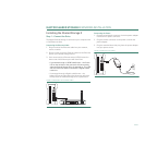
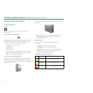
Step 2 – Power up the Drive
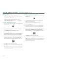
1. Press the round black button on the back panel of your
Maxtor Shared Storage Drive. The green LED (light) with
illuminate in the center of the power button.
2. Your drive will now start. The startup process can take up
to one minute to complete.
Shared Storage Drive Power/Status LED Definitions
Various LED activity will appear on your Shared Storage II
Drive when power is applied. The following tables define the
meaning/status of each LED on the back and front panels:
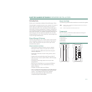
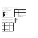
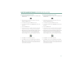
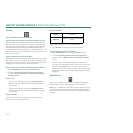
Back Panel LEDs
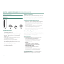
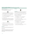
Front Panel LEDs
LED
Definition Status
Power LED
(located in
center of the
power button)
Power switch
Illuminated
– Power On
Not Illuminated
– Power Off
Ethernet LED
(located on
bottom side of
Ethernet
connector)
Shows if the drive is
connected through a 10/100 or
a 1 Gb Ethernet connection.
Left Green
– 10/100 Mbps
Ethernet connectivity
Left Amber
– 1 Gbps Ethernet
connectivity
Illuminated
– Power On
Blinking
– Network
communication is occurring
Not Illuminated
– Power Off
Activity LED
(located on top
side of Ethernet
connector)
A flashing Activity LED
indicates that the network
connection is functional and
that packets are being
transmitted or received.
Power Button
Ethernet LED
Activity LED
LED
Definition Status
Top
Power Activity
Illuminated
– Power On
Blinking
– Drive is either powering up or
shutting down
Not Illuminated
– Power Off
Center
Hard Disk Activity
Illuminated
– Power On
Blinking
– Data is being transferred to/from the
drive
Not Illuminated
– Power Off
Bottom
Network Activity
Illuminated
– Power On
Blinking
– Network communication is occurring
Not Illuminated
– Power Off
Power Activity
Hard Disk Activity
Network Activity