


3-29
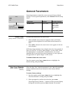
Nº51 Media Player Setup Menu
Before Using Test Images
Before using the test images, be sure the associated display and any
other devices in the path between the Nº51 Media Player and the
display are independently calibrated. This separate calibration should
not be confused with calibration using the Nº51 Media Player
generated test patterns. Independent device calibration, resulting in
the acceptance of a perfect signal, should be verified using a reference
test pattern from a device that is known to be properly calibrated.
When using test images, the Nº51 Media Player video parameters
should be adjusted to 0.
In most cases, independent device calibration requires a knowl-
edgeable technician and should be left to your system installer.
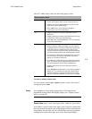
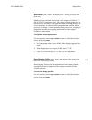
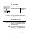
Color Bars (Setup : Video : Edit Source Profile : Test Images : Color Bars)
Color Bars are used to adjust the Color Tint and Saturation parameters
to ensure proper color output on the associated display device.
Before adjusting color controls using the Color Bars test image:
• Activate a source profile (see Select Source Profile on page 3-16.)
• Set the Nº51 Media Player’s Brightness and Contrast parameters to 0.
To adjust color controls using the Color Bars test image:
1. Select the Color Bars test pattern.
2. Evaluate the colors on the associated display device.
3. Adjust the red-to-green color balance in the image using the
Color Tint parameter of the associated device.
4. Adjust tonal values using the Saturation parameter of the
associated device.
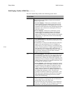
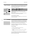
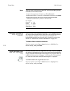
Crosshatch (Setup : Video : Edit Source Profile : Test Images : Crosshatch)
The Crosshatch test image is used to adjust the convergence of the
display or to align display geometry size and alignment. Generally,
convergence only applies to displays with three (red, green, and blue)
CRT guns or to a projection display system with three optical paths.
The Crosshatch test image appears as a matrix of horizontal and
vertical white lines on a black background. Each line is comprised of
red, green, and blue components. In order to display the lines as
white, each CRT gun, or projection system optical path, must have
the RGB video components aligned precisely over each other. By