


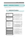

Chapter 1 Installation Procedure
9
1
1
1
.
.
.
4
4
4
D
D
D
i
i
i
s
s
s
k
k
k
A
A
A
r
r
r
r
r
r
a
a
a
y
y
y
C
C
C
o
o
o
n
n
n
f
f
f
i
i
i
g
g
g
u
u
u
r
r
r
a
a
a
t
t
t
i
i
i
o
o
o
n
n
n
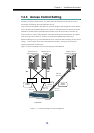
For the disk array to be connected, determine the configuration for using the data replication.
1
1
1
.
.
.
4
4
4
.
.
.
1
1
1
L
L
L
o
o
o
g
g
g
i
i
i
c
c
c
a
a
a
l
l
l
D
D
D
i
i
i
s
s
s
k
k
k
(
(
(
L
L
L
D
D
D
)
)
)
S
S
S
e
e
e
l
l
l
e
e
e
c
c
c
t
t
t
i
i
i
o
o
o
n
n
n
According to the disk capacity necessary for business or operation conditions, determine the logical
disk (LD) and hot spare configurations. For the 4000 series and the 3000 series, disk array
configurations are executed by maintenance personnel and therefore should be determined before
installation. To improve the access performance and keep tolerance against physical disk (PD) faults,
assign MV and RV to different ranks. MV and RV to be paired should have the same LD capacity.
If LD configuration is changed after starting the server, be sure to execute the create/display Volume
List command (iSMvollist -cr) after changing the configuration.
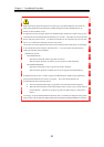
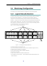
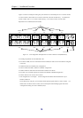
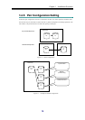
Figure 1-3 shows an example of setting five pairs.
Figure 1-3 LD Configuration Example (2000 series)
• The PD group number for PD and RANK is 00.
• One LD is associated with one RANK. (The whole area for one RANK is assigned to one LD.)
• LD00 and LD05 are in RAID5 (4+P) configuration.
• LD01 to LD04 and LD06 to LD09 are in RAID1 configuration.
• Each DE has two spare disks.
• LD00 to LD04 are used for MV and LD05 to LD09 are for RV.
* This configuration is just an example. Actual configuration should be determined based on your
business conditions.
PD01 PD00 PD03 PD02 PD05PD04 PD07PD06 PD09PD08 PD0b PD0a PD0dPD0c PD0e
PD11 PD10 PD13 PD12 PD15PD14 PD17PD16 PD19PD18 PD1b PD1a PD1dPD1c PD1e
Spare Disks
LD00 LD01 LD02 LD03 LD04
RANK00 RANK01 RANK02 RANK03 RANK04
LD05 LD06 LD07 LD08 LD09
RANK05 RANK06 RANK07 RANK08 RANK09
MV
RV