


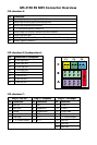


MS 4150 RS MP3 Connector Overview
ISO chamber A:
Pin Connection
A1 Input digital speedometer signal / SDVC / GALA
A2 Switch input reversing signal (reversing light plus)
A3 Switch input telephone mute function
A4 + 12 V permanent positive; terminal 30
A5 Switch output for electronic antenna /relay motor antenna
A6 Switch input pilot light
A7 +12 V ignition positive / ACC; terminal 15 (without switch-off on starting engine)
A8 Battery negative; terminal 31
ISO chamber B (loudspeakers):
Pin Connection to loudspeaker
B1 + Rear right (RR+)
B2 – Rear right (RR-)
B3 + Front right (FR+)
B4 – Front right (FR-)
B5 + Front left (FL+)
B6 – Front left (FL-)
B7 + Rear left (RL+)
B8 – Rear left (RL-)
ISO chamber C:
Plug C1 / line out Plug C2 / telephone Plug C3 / CD changer
Pin Connection Pin Connection Pin Connection
C1 Rear left C7 D2B – C13 CD UART +
C2 Rear right C8 Telephone in C14 CD UART –
C3 Ground C9 Telephone Ref. C15 CD UART GND
C4 Front left C10 D2B + C16 + 12 V permanent
C5 Front right C11 RC3 – C17 + 12 V Switch output
C6 + 12 V Switch output C12 RC3 + C18 SPDIF Line
C19 SPDIF GND
C20 SPDIF GND
Fuse
14
36
25
710
912
811
13 16
15 18
14 17
19
20
C1 C2 C3
B
A
1
2
3
4
5
6
7
8
1
2
3
4
5
6
7
8
C