


■
Reversing signal (A2):
☞
Connect pin A2 to a suitable reversing signal point (positive lead of reversing lamp).
Note: Operation of the navigation system is not possible without a reversing signal.
The absence of a reversing signal may lead to inaccurate navigation.
■
Telephone mute function (A3), optional:
☞
Connect pin A3 to the mute function output of the car phone or the hands-free
unit. When the telephone is in use, the radio is muted or the telephone
conversation is amplified via the car loudspeakers. See also “Green connector C2”
on the following page.
■
12 V permanent positive (A4):
☞
Connect pin A4 to a suitable connector with 12 V permanent positive.
A
This connection should be rated for a current of at least 10 A.
■
Electronic antenna / motor antenna (A5), optional:
☞
Connect pin A5 to the supply lead of an electronic antenna or to the control lead of
a motor antenna.
A
Do not use this connection to supply the antenna motor.
■
Pilot lighting (A6), optional:
☞
Connect pin A6 to a suitable connector of the low-beam positive lead.
✎
When the low beam is switched on, the pilot lighting at the volume control is
illuminated, even when the radio is switched off.
■ 12 V ignition positive (A7):
☞
Connect pin A7 to a suitable 12 V circuit switched through the ignition.
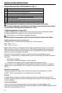
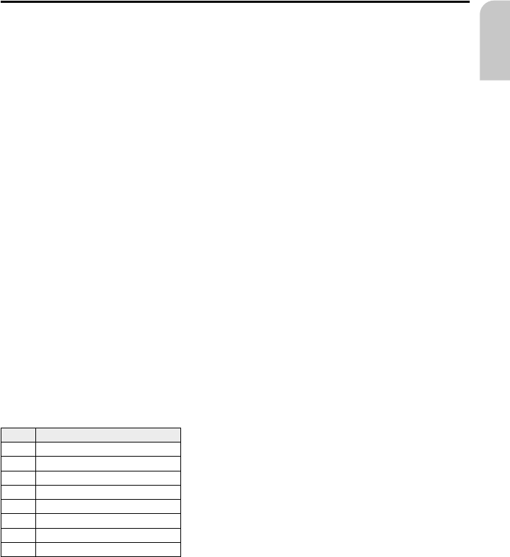
Connection overview ISO chamber B (loudspeakers), Fig. 3:
Pin Connection to loudspeaker
B1 + Rear right (RR+)
B2 - Rear right (RR-)
B3 + Front right (FR+)
B4 - Front right (FR-)
B5 + Front left (FL+)
B6 - Front left (FL-)
B7 + Rear left (RL+)
B8 - Rear left (RL-)
A
Use only loudspeakers of 4 Ohms impedance.
A
Do not connect the loudspeakers to earth.
A
Do not connect the booster/amplifier directly to the loudspeaker outputs.
A
Do not connect loudspeakers via an external fader.
To check the correct connection of the loudspeakers the function “Loudspeaker Test”
in the “INITIALISATION” menu can be performed.
INSTALLATION INSTRUCTIONS
17
English