


Filename [DVM70S_05Name.fm]
Masterpage:Left0
18 EN
Page 18 Friday, 6 May 2005 12:06
INSTALLING YOUR NEW UNIT
It’s essential that your unit be properly connected.
1 Make sure the package contains all of the accessories listed in
ASPECIFICATIONSB (A pg. 88).
2 Place the unit on a stable, horizontal surface.
3 Connect the unit to a TV depending on the TV and cables you
use.
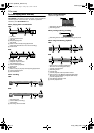
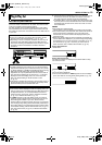
8 AV Connection
To connect to a TV with AV input connectors ^
A Disconnect the TV aerial cable from the TV.
B Connect the TV antenna cable to the [VHF/UHF IN] connector
on the rear panel of the unit.
C Connect the [VHF/UHF OUT] connector on the rear panel of the
unit and the TV’s antenna connector with the supplied RF
cable.
D Connect the supplied audio/video cable between the [AUDIO/
VIDEO OUTPUT] connectors on the rear panel of the unit and
the TV’s audio/video input connectors.
● if your TV is equipped with a BNC video connector, connect an
optional BNC video cable between the unit’s BNC [VIDEO
OUTPUT] connector and the TV’s BNC VIDEO input connector.
8 S-Video Connection
To connect to TV’s S-VIDEO input and AUDIO input
connectors ^
A Perform A – C of AAV ConnectionB in the left column.
B Connect the unit’s [S-VIDEO OUTPUT] connector to the TV’s
S-VIDEO input connector.
C Connect the unit’s [AUDIO OUTPUT] connectors to the TV’s
AUDIO input connectors.
● If your TV is not stereo-capable, use the unit’s [AUDIO
OUTPUT] connectors to connect to an audio amplifier for Hi-Fi
stereo sound reproduction.
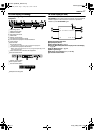
8 Component Video Connection
To connect to TV’s component video input connectors ^
A Perform A – C of AAV ConnectionB in the left column.
B Connect the unit’s [COMPONENT VIDEO OUT (Y/P
B
/P
R
)]
connectors to the TV’s component video input connectors.
C Connect the unit’s [AUDIO OUTPUT] connectors to the TV’s
AUDIO input connectors.
● You can obtain high-quality component video pictures.
● The [COMPONENT VIDEO OUT (Y/P
B
/P
R
)] connectors do not
output DV signals.
● If your TV is not stereo-capable, use the unit’s [AUDIO
OUTPUT] connectors to connect to an audio amplifier for Hi-Fi
stereo sound reproduction.
● By using the component video connection, you can view the
images in the progressive mode. For switching to the
progressive mode, refer to AScan Mode Set (HDD & DVD Deck
Only)B (A pg. 76).
4 Plug the end of the AC power cord into an AC outlet.
This unit performs Plug & Play Set automatically. (A pg. 19)
● The clock and tuner channels will automatically be set when the
antenna is connected and when the AC power cord is first
connected to an AC outlet. (If AAUTOB and the channel indicator
are displayed on the front display panel before the unit is
powered on, the clock and tuner channels are being set
automatically. Wait for the time to be displayed on the front
display panel before turning on the unit.)
● ALOADINGB blinks on the front display panel when the AC plug
of the AC power cord is connected into a AC outlet and it takes
approximately 50 seconds for the unit to be turned on. This is
not a malfunction.
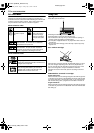
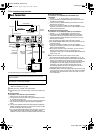
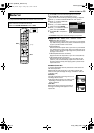
Basic Connections
ATTENTION:
Connect the AC plug only after all connections to the TV has
been completed.
THESE STEPS MUST BE COMPLETED BEFORE ANY VIDEO
OPERATION CAN BE PERFORMED.
Back of unit
To [VHF/
UHF IN]
TV
AC outlet
Antenna or Cable
Flat feeder
Coaxial cable
To
[COMPONENT
VIDEO OUT (Y/
P
B
/P
R
)]
To
[VHF/
UHF
OUT]
BNC video
cable (not
supplied)
S-video cable
(not supplied)
Component
video cable
(not supplied)
To
[VIDEO
OUTPUT]
To
[AUDIO/
VIDEO
OUT]
Matching transformer
(not supplied)
AC power cord
Audio/Video
cable
(supplied)
RF cable
(supplied)
To
[S-VIDEO
OUTPUT]
DVM70S_00.book Page 18 Friday, May 6, 2005 12:06 PM