


User's Guide Fireface 800 © RME
19
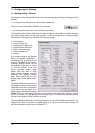
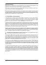
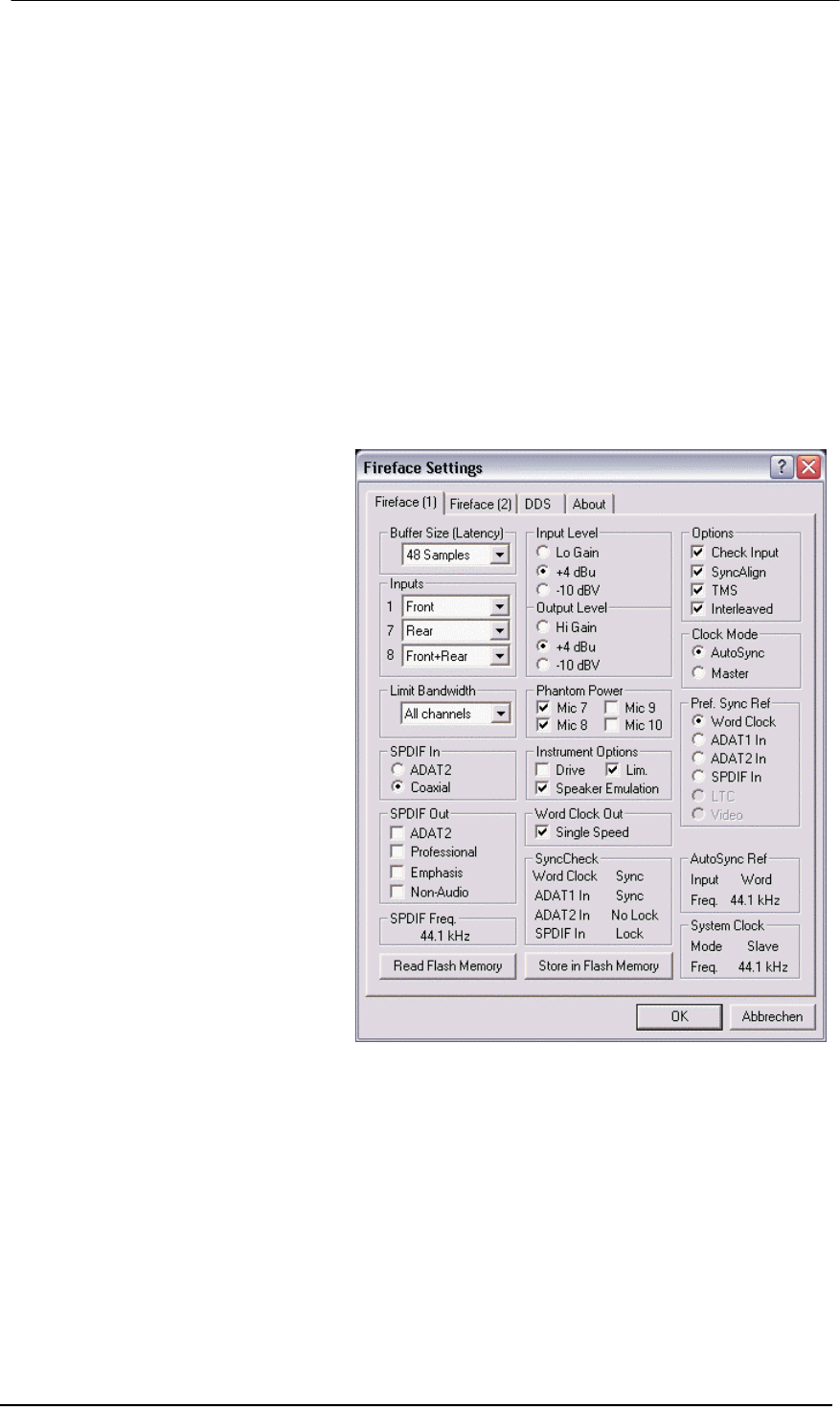
Buffer Size
The setting Buffer Size determines the latency between incoming and outgoing ASIO and GSIF
data, as well as affecting system stability (see chapter 13/14). Under Windows MME this setting
determines the DMA buffer size (see chapter 12.3). GSIF and MME can be set from 48 to 256
samples. Above 256, only ASIO is effected
Inputs
Input selection for the channels 1, 7 and 8. Channel 1 can be the front instrument input, or the
rear TRS jack, or both simultaneously. Channel 7/8 can be the front microphone input, or the
rear TRS jack, or both simultaneously.
Limit Bandwidth
Allows to reduce the amount of bandwidth used on the FireWire bus. See chapter 11.4.
All channels (default) activates all 28 input and output channels.
Analog + SPDIF + ADAT1 disables channels 21–28 (ADAT2).
Analog + SPDIF activates all 10 analog channels plus SPDIF.
Analog 1-8 activates only the first eight analog channels.
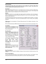
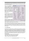
SPDIF In
Defines the input for the SPDIF sig-
nal. 'Coaxial' relates to the RCA
socket, 'ADAT2' to the second optical
TOSLINK input.
SPDIF Out
The SPDIF output signal is constantly
available at the phono plug. After
selecting 'ADAT2' it is also routed to
the second optical TOSLINK output.
For further details about the settings
‘Professional’, ‘Emphasis’ and ‘Non-
Audio’, please refer to chapter 29.2.
SPDIF Freq.
Displays the sample rate of the signal
at the SPDIF input.
Input Level
Defines the reference level for the
rear analog inputs 1-8.
Output Level
Defines the reference level for the
rear analog outputs 1-8.
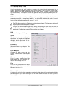
Phantom Power
Phantom power (48V) can be selected for each microphone input seperately.
Instrument Options
Drive activates 25 dB additional gain for maximum sustain and brute distortion.
Lim. activates a soft-limiter with a threshold of –10 dBFS. Note: The Limiter can only be
switched off with input selection Front.
Speaker Emulation removes low frequency noise and cuts off higher frequencies.