1-5
User Guide for Cisco Digital Media Encoder 2200
OL-17938-01
Chapter 1 Installing the Cisco Digital Media Encoder 2200
Installation
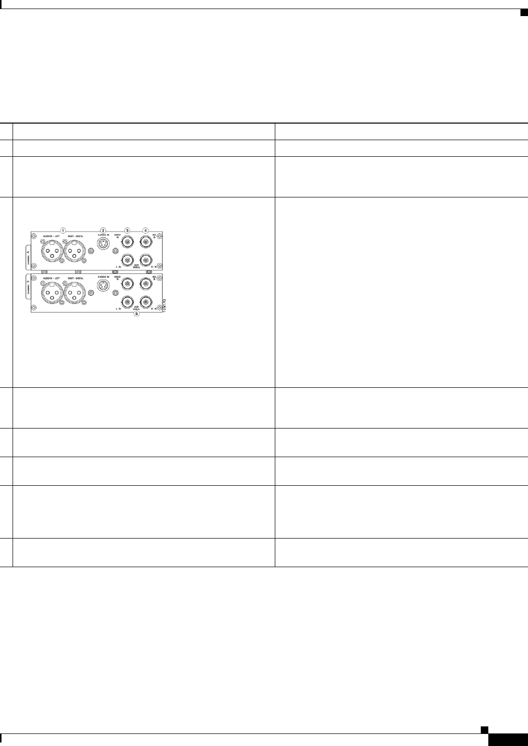
Figure 1-1 shows the rear panel of the encoder. Using the reference chart and images in Table 1-1, you
can connect the appropriate device and power to the encoder.
Table 1-1 Rear Panel Reference
— Port Description
1 AC Power Input Provides system power.
2 Video Test Ports BNC connector for composite video IN/OUT. Allows you
to connect a video test signal, such as a color bar generator,
to calibrate the video settings for video capture sessions.
3 Channel A & B AV Inputs Each AV Input channel provides the following input ports:
1. Left/Right XLR connector for balanced audio sources;
right XLR connector for AES/EBU audio
2. Mini-DIN connector for S-Video sources
3. BNC connector for composite video sources
4. BNC connector for SDI Video Sources with embedded
SDI audio
5. Left/Right BNC connectors for unbalanced audio
sources
4 Alarm Relay Connector Use this port to connect an external device (such as an
audible bell or buzzer) so that, if the system fails, it will
trigger an external audible sound.
5 Network Ports (Line 1 & 2) Dual Ethernet ports provide redundant connections to your
network.
6 Auxiliary VGA Connector Use this port to connect an external VGA monitor so that
you can view the Operating System Interface.
7 Control RS-422 Connector (FUTURE) 9-pin D connector. Allows you to control the
encoder via RS-422 protocols, providing integration into a
broadcast studio master control center. This is a standard
RS-422 port that can be used with deck control software.
8 USB 2.0 Connectors Use these ports to connect USB control devices, such as a
keyboard and mouse or USB memory devices.


