


48 TASCAM HS-8
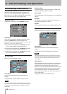
Remote settings (REMOTE SETUP)
Make settings for PARALLE connector AUX 1-3 functions
and the RS-232C and RS-422 control connectors. The
REMOTE
SETUP
screen has a
PARALLEL
page, an
RS-232C
page, and an
RS-422
page. Touch the tabs at the bottom
of the screen to open the corresponding page.
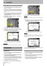
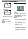
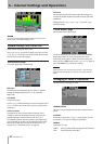
PARALLEL TAB
Set the AUX 1-3 functions of the PARALLE connector.
AUX Assign
Touch a knob, making the background become yellow
and turn the DATA dial to set the parameter. The
parameters that can be selected include
F.FWD
,
REW
,
MARK
,
MARK
SKIP-
,
MARK
SKIP+
and
ONLINE.
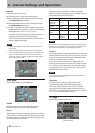
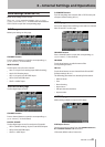
AUX1 Function: Set the function of PARALLEL connector
pin 17 (AUX1). (Default setting: MARK SKIP +)
AUX2 Function: Set the function of PARALLEL connector
pin 18 (AUX2). (Default setting: MARK SKIP –)
AUX3 Function: Set the function of PARALLEL connector
pin 19 (AUX3). (Default setting: MARK)
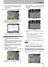
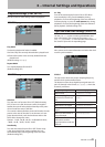
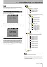
RS-232C page
Make RS-232C transmission settings.
Serial Mode
Set the serial connection mode with the following
buttons.
Setting buttons: “RS-232C” (default value), “RS-422”
NOTE
The RS-232C and RS-422 connectors cannot both be used at the
same time. Only the connector selected with this setting functions.
This setting is synchronized with the “Serial Mode” item on the
RS-422 page.
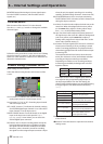
Baud Rate (bps)
Set the transmission speed. The options are 4800, 9600,
19200 and 38400 bps (default setting).
Data Length
Set the data length in bits. The options are 7 and 8 (default
setting).
Parity Bit
Set whether or not there is a parity bit. The options are
NONE
(default setting),
EVEN
and
ODD
.
Stop Bit
Set the stop bit. The options are 1 (default setting) and 2.
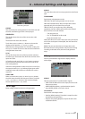
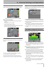
RS-422 page
Make communication settings for RS-422 serial control.
Serial Mode
Set the serial connection mode with the following
buttons.
Setting buttons: “RS-232C” (default value), “RS-422”
NOTE
The RS-232C and RS-422 connectors cannot both be used at the
same time. Only the connector selected with this setting functions.
This setting is synchronized with the “Serial Mode” item on the
RS-232C page.
Video Resolve
When slaving this unit to a VCR, video sync signals might
be used instead of word sync signals for the common
standard clock. In the same way as with word sync
signals, you can select whether the video clock is followed
(synchronizing the beginning of time code frames with
video signal frame edges) or it is independent of the
frame clock. This must be turned ON to control this unit
from a video editor.
Setting buttons: “OFF”, “ON” (default value)
6 – Internal Settings and Operations