


TASCAM HS-8 13
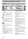
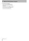
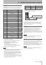
PARALLEL connector
The PARALLEL connector on the rear panel allows external
control of this unit. The pin assignments are as follows.
Pin No. Function In/Out
1 GND
2 PLAY/Flash 1 In
3 STOP/Flash 2 In
4 RECORD/Flash 3 In
5 SKIP FWD/Flash 4 In
6 SKIP BWD/Flash 5 In
7 FLASH LOAD (STOP) In
8 FADER START In
9 FLASH Tally Out
10 READY Tally Out
11 RECORD Tally Out
12 STOP Tally Out
13 PLAY Tally Out
14 REMOTE Select In
15 PAUSE/Flash 6 In
16 CALL/Flash 7 InIn
17 AUX1/Flash 8 In
18 AUX2/Flash 9 In
19 AUX3/Flash 10 In
20 Flash Page In
21 Reserved
22 CF1 Tally Out
23 ONLINE Tally Out
24 CF2 Tally Out
25 +5V*
In: Command input, for transport control
Internal circuit, +5V pull-up
Operates with low commands of 50 msec or more
Out: Command output, for tally output
The internal circuit is open collector (output
impedance 10Ω)
Low command output when operating
20 V dielectric strength, 35 mA maximum current
*
+5V: 50 mA maximum supplied current
NOTE
The FLASH LOAD (STOP) (pin 7) functions are FLASH LOAD when
•
stopped and STOP during playback and when paused.
When Remote Select (Pin 14) is high, the input pins that have
•
two commands separated by a “/” (pins 2–6 and 15–19) in the
above table will perform the rst-listed function, and can be
used as conventional parallel controllers.
When this pin is low, the above-listed input pins will function as
ash start keys. Moreover, the key assignments will be as follows
according to the high/low state of pin 20.
#14 #20 Flash-start take
Low High 1–10
Low Low 11–20
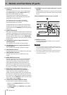
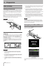
The following example is of a connection that uses a fader to
•
start and stop playback of this device.
For information about the assignment of AUX1-3 (pins
17-19) functions, see the “PARALLEL tab” of the REMOTE
SETUP screen on page 48.
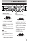
RS-232C Connector
The RS-232C connector on the rear panel can be
connected to an RS-232C connector on a computer to
allow control of this unit from that computer.
Makes settings related to communication on the REMOTE
SETUP screen RS-232C page. (See “RS-232C page” on page
48.)
NOTE
Please contact TASCAM customer support for information about
this unit’s RS-232C command protocol.
RS-422 connector
You can control this unit remotely by connecting the
RS-422 connector on its rear panel to a controller or editor
compatible with SONY P2 protocol (RS-422).
Make settings related to operation on the REMOTE SETUP
screen RS-422 page. (See “RS-422 page” on page 48.)
NOTE
Please contact TASCAM customer support for information about
this unit’s protocol compatibility.
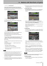
2 − Names and functions of parts