


12 TASCAM HS-8
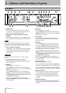
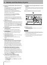
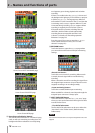
n DIGITAL I/O (AES/EBU) INPUT A/B and OUTPUT L/R
connectors
These XLR balanced connectors are for digital audio
input (INPUT A/B) and output (OUTPUT L/R) in AES/
EBU (AES3-2003/IEC60958-4) format.
Transmission occurs at double speed when the
sampling frequency is 88.2 and 96 kHz and at quad
speed when 176.4 and 192 kHz.
The digital input section includes a sampling
rate converter that is compatible with sampling
frequencies between 32–216 kHz
The digital output section outputs the stereo signal
mixed in this unit or the monitoring signal (the same
sound output from the PHONES jack, including soloed
tracks, etc.).
m SIGNAL GND terminal
When using a TASCAM RC-HS20PD remote control (sold
separately), depending on the operating environment,
the color display might flicker or noise might be heard
when monitoring. If this occurs, use the SIGNAL GND
terminal. (Please prepare a wire to use with the SIGNAL
GND terminal.)
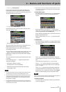
,CASCADE IN connector (support planned in a
version upgrade)
This connector is for cascade connection input.
. CASCADE OUT connector (support planned in a
version upgrade)
This connector is for cascade connection output.
/ TIME CODE IN connector
This BNC-type connector is for SMPTE time code input.
! TIME CODE OUT connector
This BNC-type connector is for SMPTE time code
output.
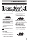
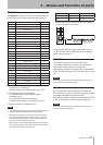
@ WORD/VIDEO IN connector
This BNC-type connector is for word clock and video
reference signal input. You can input a word clock
signal (44.1 kHz, 48 kHz, 48 kHz pull-down, 48 kHz
pull-up, 88.2 kHz, 96 kHz, 176.4 kHz, 192 kHz) or a
video reference signal (NTSC/PAL black burst signal,
HDTV Tri-Level signal). You can also use the switch to
the right to set whether or not to terminate with 75Ω.
# WORD/VIDEO THRU, WORD OUT connector
This BNC-type connector is for word clock thru or
output and video reference signal thru. You can
output a word clock signal (thru, 44.1 kHz, 48 kHz, 48
kHz pull-down, 48 kHz pull-up, 88.2 kHz, 96 kHz, 176.4
kHz, 192 kHz) or a video reference signal (IN connector
signal thru). Use the THRU/OUT switch to set the signal
output. (OUT is only for WORD.)
$ 75Ω OFF/ON and THRU/WORD OUT switch
Use this switch to make the following settings.
Whether or not
•
WORD/VIDEO IN has termination
resistance (75Ω)
The
•
WORD/VIDEO output THRU/OUT setting (OUT is
only for WORD)
% ETHERNET connector (support planned in a version
upgrade)
Use this Ethernet connector to connect with a network
for file transfer and to control this unit from an external
source.
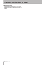
When the REMOTE Connector cover is removed
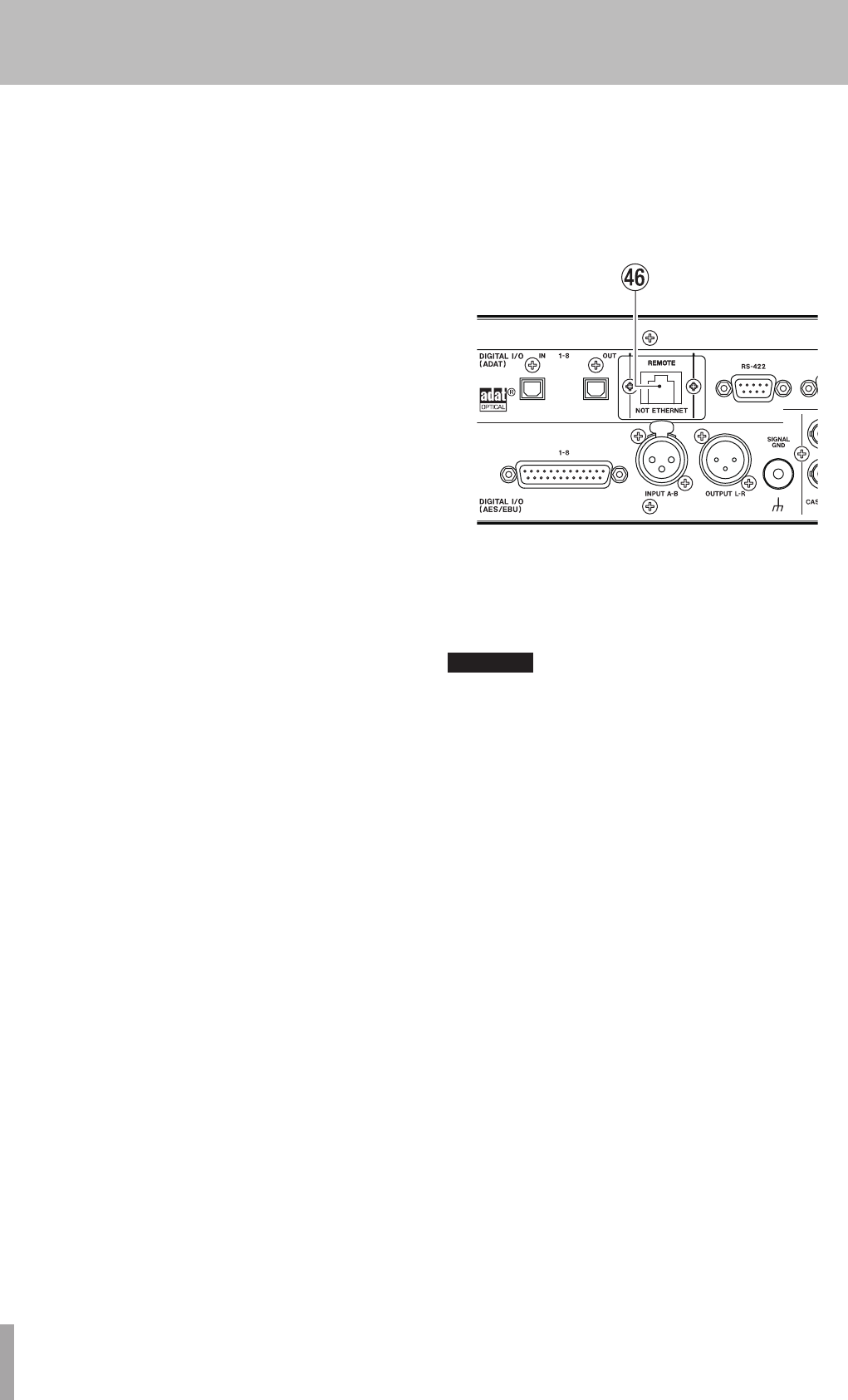
^ REMOTE connector
Connect a dedicated RC-HS20PD remote controller
(sold separately) here.
CAUTION
This is not an Ethernet connector (LAN, etc.). Never connect it
•
to a network using an Ethernet cable. Doing so could cause this
unit or network devices to malfunction.
When the unit is shipped from the factory, this connector has
•
a cover attached with screws in order to prevent accidental
connection to a network.
2 − Names and functions of parts