


Chapter 7 Setup Menu
Chapter 7 Setup Menu 7-7
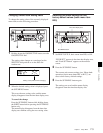
7-3 Basic Menu
a) When setting items 002, 003, 009 and 011 watch the
monitor screen, and adjust to the required state.
b) When displaying time code values, there is a slight time
delay. Therefore, when creating a tape for off-line
editing, the information inserted in the upper half of the
screen may be delayed by one frame.
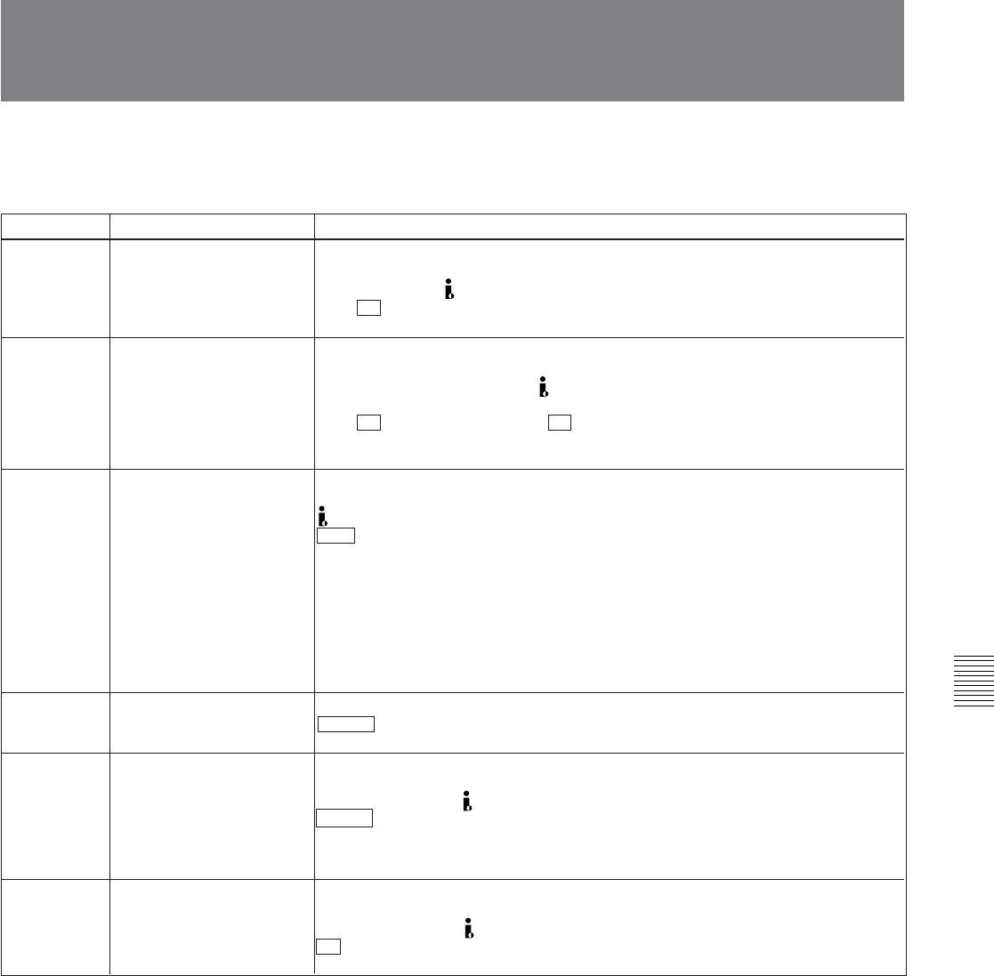
The basic menu contains the following items.
In the “Settings” column of the table, the factory
default settings are indicated by an enclosing box.
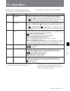
011
a)
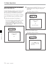
CHARACTER V-SIZE Determines the vertical size of characters such as time code output from the
COMPOSITE (SUPER) output connector, SDI (SUPER) output connector
(J-10SDI/30SDI), or DV connector for superimposed display on the monitor.
×1: Standard size
×2: 2 times standard size
009
a)
CHARACTER TYPE Determines the type of characters such as time code output from the
COMPOSITE (SUPER) output connector, SDI (SUPER) output connector
(J-10SDI/30SDI), or DV connector for superimposed display on the monitor.
WHITE : White letters on a black background.
BLACK: Black letters on a white background.
W/OUT: White letters with black outlines.
B/OUT: Black letters with white outlines.
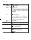
Item number Item name Settings
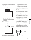
002
a)
CHARACTER H-
POSITION
Adjust the horizontal screen position of the character information output from the
COMPOSITE (SUPER) output connector, SDI (SUPER) output connector (J-
10SDI/30SDI), or DV connector for superimposed display on the monitor.
00 ... 10 ... 08: The value 00 is for the far left of the screen and 08 for the far right.
Increasing the value moves the position of the characters to the right.
003
a), b)
CHARACTER V-
POSITION
Adjust the vertical screen position of the first line of the character information
output from the COMPOSITE (SUPER) output connector, SDI (SUPER) output
connector (J-10SDI/30SDI), or DV connector for superimposed display on the
monitor.
00 ... 11 ... 14 (525 mode)/00 ... 14 ... 17 (625 mode): The hexadecimal value 00
is for the top of the screen and increasing the value lowers the position of the
characters.
005 DISPLAY INFORMATION
SELECT
Determines the kind of character information to be output from the COMPOSITE
(SUPER) output connector, SDI (SUPER) output connector (J-10SDI/30SDI), or
DV connector for superimposed display on the monitor.
OFF : Displays no character information.
T&STA : Time data display information and the unit’s status.
T&UB: Time data display information and the user bits.
T&CTL: Time data display information and CTL.
T&T: Time data display information and time code (LTC or VITC).
TIME: Time data display information only
If there is an overlap between the setting of this item and the setting of the control
panel, it is automatically avoided. For example, if CTL is selected on the control
panel and this menu item setting is T&CTL, CTL and LTC will be output.
007 TAPE TIMER DISPLAY
Determines whether to display the CTL counter in 12-hour mode or 24-hour mode.
+ –12H : 12-hour mode
24H: 24-hour mode