


Chapter 2 Location and Function of Parts
2-10 Chapter 2 Location and Function of Parts
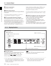
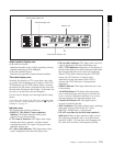
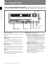
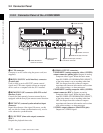
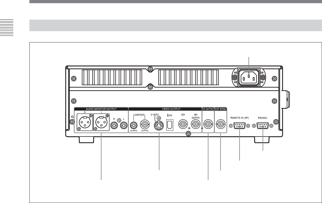
2-2-2 Connector Panel of the J-10SDI/30SDI
2 RS232C connector
6 VIDEO OUTPUT
connectors
7 AUDIO MONITOR
OUTPUT connectors
1 AC IN connector
3 REMOTE IN (9P) connector
4 EXT SYNC input connector
5 TC OUTPUT connector
1 AC IN connector
Connects to an AC outlet using the power cord (not
supplied).
2 RS232C (RS-232C serial interface) connector
(D-sub 9-pin)
Used to send or receive RS-232C remote control
signals and VTR status signals to/from an external
device such as a computer with the JZ-1 installed.
3 REMOTE IN (9P) connector (RS-422A serial
interface, 9-pin)
Controls the unit remotely from an external device
equipped with the Sony 9-pin remote control function.
4 EXT SYNC (external synchronization) input
connector
Inputs the reference video signal. However, on this
unit, use this for frame synchronization only, not for
color subcarrier synchronization.
5 TC OUTPUT (time code output) connector
(BNC)
Outputs the playback time code.
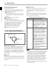
6 VIDEO OUTPUT connectors
COMPOSITE (analog composite video) (SUPER)
output connector (phono jack): Outputs an analog
composite video signal. When the basic menu
item 005, DISPLAY INFORMATION SELECT,
of the setup menu is set as anything other than
OFF, the output from this connector outputs
superimposed character information such as time
code, menu settings, or alarm messages.
COMPOSITE (analog composite video) (SUPER)
output connector (BNC): Outputs an analog
composite video signal. When the basic menu
item 005, DISPLAY INFORMATION SELECT,
of the setup menu is set as anything other than
OFF, the output from this connector outputs
superimposed character information such as time
code, menu settings, or alarm messages.
S VIDEO output connector (Mini-DIN 4-pin):
Outputs an S VIDEO signal.
2-2 Connector Panel