


Additional Features
43
UDP-89 User Manual Version 2.0 www.hhb.co.uk
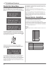
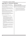
Abridged command set
The commands listed in the below will perform the same
function as their equivalent front panel buttons. For all other
commands, data requests and responses, please refer to the
UDP-89’s full RS232 protocol specification.
Note: All commands are shown here in hex format.
COMMAND DATA STRING (HEX)
ENABLE REMOTE MODE (see note 1) 7E 08 05 62 01 01 01 FF
DISABLE REMOTE MODE (see note 1) 7E 08 05 62 01 01 00 FF
STANDBY MODE ON 7E 08 05 62 01 02 01 FF
STANDBY MODE OFF 7E 08 05 62 01 02 00 FF
PLAY/PAUSE 7E 07 05 62 02 01 FF
STOP 7E 07 05 62 02 02 FF
PREVIOUS TRACK 7E 07 05 62 02 06 FF
NEXT TRACK 7E 07 05 62 02 07 FF
FFWD 7E 07 05 62 02 04 FF
FREW 7E 07 05 62 02 03 FF
EJECT 7E 07 05 62 02 08 FF
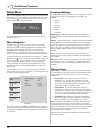
MENU 7E 08 05 62 14 03 00 FF
CURSOR LEFT
7E 0B 05 62 14 01 00 00 00
01 FF
CURSOR RIGHT
7E 0B 05 62 14 01 00 01 00
00 FF
CURSOR UP
7E 0B 05 62 14 01 01 00 00
00 FF
CURSOR DOWN
7E 0B 05 62 14 01 00 00 01
00 FF
MARK/ENTER 7E 07 05 62 14 02 FF
VOLUME ADJUSTMENT:
e.g. SET VOLUME TO 0dB
(see note 2)
7E 08 05 62 13 01 5B FF
INDIVIDUAL CHANNEL TRIM:
e.g. SET LEFT CHANNEL TO 0dB
(see note 3)
7E 0D 05 62 13 02 00 00 0B
00 00 00 FF
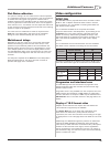
Note 1: The UDP-89’s RS232 port must be enabled by the REMOTE ON command
before any further RS232 commands will be accepted. Once REMOTE MODE has
been enabled, neither the front panel controls nor the RC-89 handset will operate and
operation of the UDP-89 can only be controlled with the RS232 Port or the Parallel
Port. REMOTE MODE must be disabled before the front panel controls and handset
will function again.
Note 2: Volume adjustment is possible via the RS232 port over the full range of
control, from -90 dB to 0 dB, in 1 dB steps. Byte 7 sets the actual volume, and
should be in the hex range 01(-90 dB) to 5B (0 dB, max. volume). Setting the byte to
00 mutes the audio.
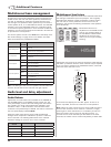
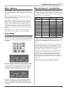
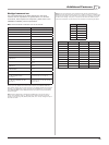
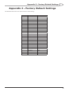
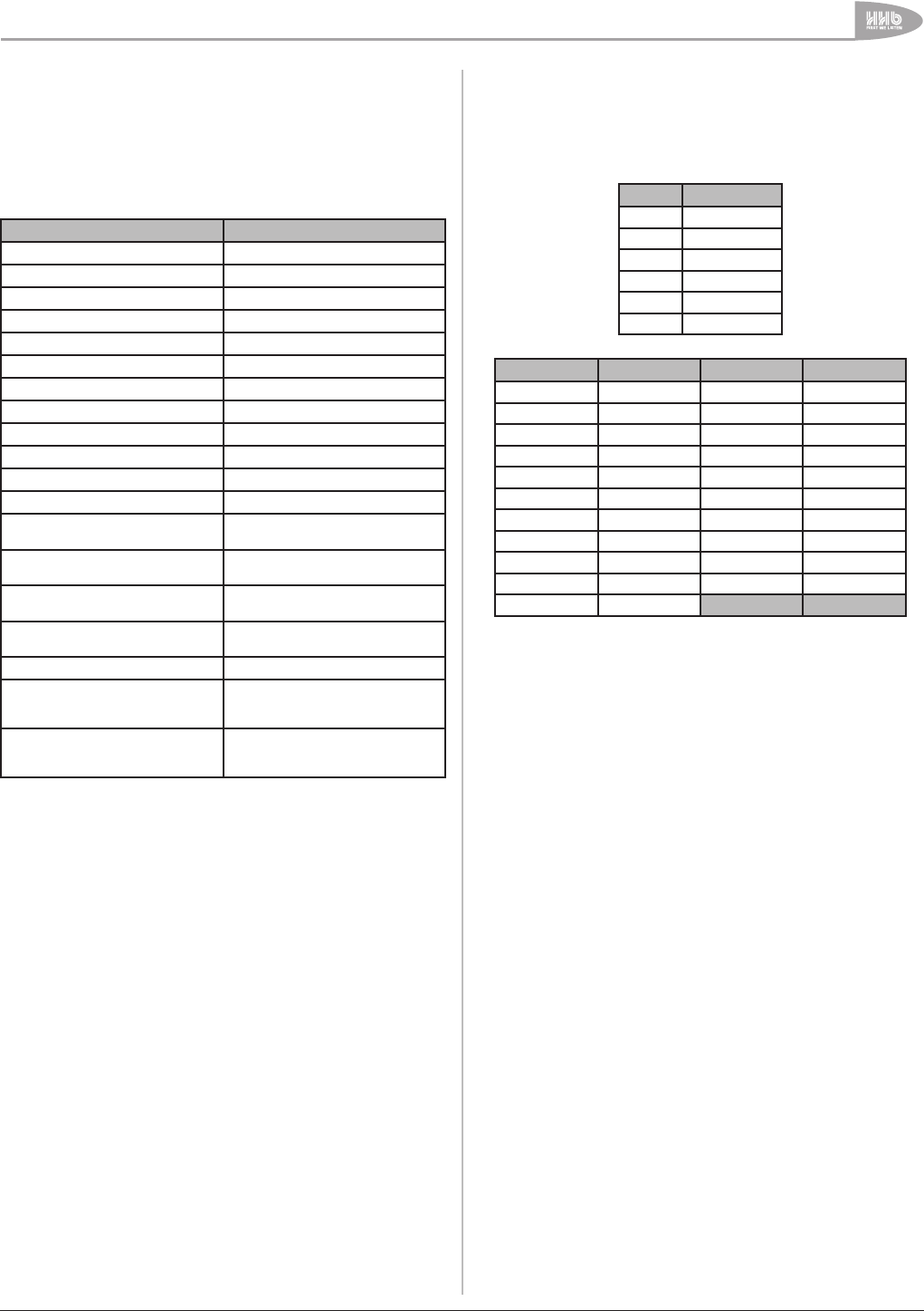
Note 3: Level trim adjustment of the individual audio channels is possible via the
RS232 port over the full range of control, from -10 dB to +10 dB, in 1 dB steps. The
value of one of the bytes 7 to 12 should be in the range 01 (-10 dB) to 15 (+10 dB)
to effect a level change. The byte (7 to 12) with the non-zero value determines the
channel to be adjusted. The valid codes are summarised in the following two tables:
BYTE CHANNEL
7 Centre
8 Sub-woofer
9 Front Left
10 Front Right
11 Surround Left
12 Surround Right
BYTE VALUE LEVEL (dB) BYTE VALUE LEVEL (dB)
01 -10 0C +1
02 -9 0D +2
03 -8 0E +3
04 -7 0F +4
05 -6 10 +5
06 -5 11 +6
07 -4 12 +7
08 -3 13 +8
09 -2 14 +9
0A -1 15 +10
0B 0
Setting one of the bytes 7 to 12 to 00 mutes the corresponding channel.