


32 Altitude 300-2™ Getting Started Guide
Hardware Installation
through the lock hasp to keep it from falling. Failure to secure the unit is
hazardous.
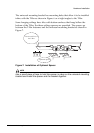
Connect the external antenna cables and the powered Ethernet cable to the
Altitude 300-2d
™
.
WARNING!
The plastic cover and the antenna shrouds have not been tested for use in a
plenum space. Do not use them for above the ceiling installations.
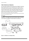
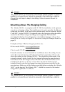
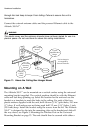
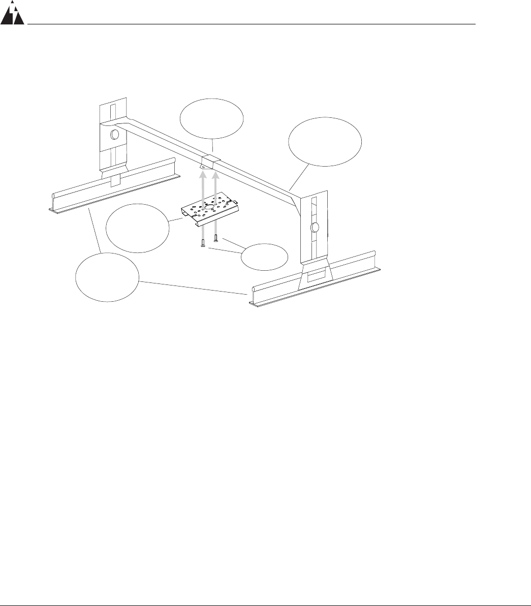
Figure 11: Above the Ceiling Box Hanger Mount
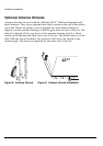
Mounting on A Wall
The Altitude 300-2
™
can be mounted on a vertical surface using the universal
mounting bracket supplied. The vertical position should be with the Ethernet
cable and lock hasp pointing up. Select the location for the unit and use the
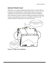
bracket as a template to mark the holes in the ceiling. For each of the four
plastic anchors supplied with the unit, drill 4.8 mm (3/16”} pilot holes, 24.5 mm
(1”) deep. If wall anchors are not being used drill 3.2 mm (1/8”) holes, 1 inch
(25.4 mm) deep. Install the bracket using the screws from the kit. The Altitude
300-2
™
is designed to slip into the mounting slots on the bracket and slide all
the way down, see Figure 5: Mounting the Wireless Port on the Universal
Mounting Bracket on page 23. The unit should then be secured with either a
Hanging
Ceiling
T-Bars
Universal
Mounting
Bracket
Typical
Adjustable Box
Hanger
Box Hanger
Bracket
Fasteners
The box hanger is
not supplied by
Extreme Networks.