


22 Altitude 300-2™ Getting Started Guide
Hardware Installation
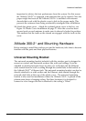
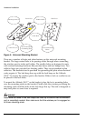
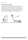
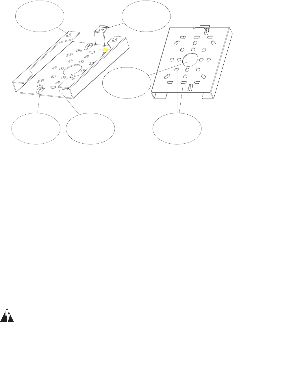
Figure 4: Universal Mounting Bracket
There are a number of holes and other features on the universal mounting
bracket. The large central hole is for passing cables through when connecting
the wireless port to in-the-wall cables. The smaller holes are designed to mate
with various fastening hardware like junction boxes and box hanger bars. Two
cable tie loops are provided for dressing cables. They accept standard nylon
cable ties. The threaded stud is provided for grounding the plate when electrical
codes require it. The lock hasp lines up with the lock hasp on the Altitude
300-2
™
. It secures the wireless port to the bracket. Either a lock or a cable tie can
be placed in the lock holes.
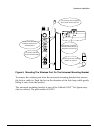
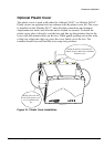
To mount the Altitude 300-2
™
on the bracket, place the box's mounting holes
over the mounting studs on the bracket. Firmly slide the wireless port along the
mounting studs until the holes in the lock hasps line up. The unit is designed to
snap into place so some force is required.
WARNING!
Make sure the holes in the lock hasps are lined up to ensure that the wireless
port is completely seated. Also make sure that the wireless port is engaged on
all three mounting studs.
Mounting Stud (x3)
Cable Tie (x2)
10-24 Threaded
Grounding Stud
Cable Hole
Padlock Hole
Various Mounting
Holes
Front View Wall View