15
2
7 ¥D¾÷ªº¦U³¡¦ì»¡©ú (¤-)
5. Player Controls (5)
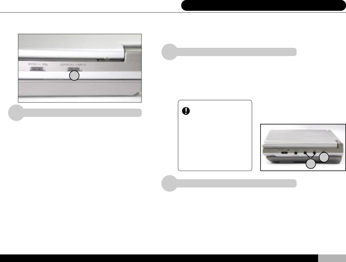
INPUT - OUTPUT Switch
Moving the switch either to the left or right will set the player to provide
input or output signals (refer to section 1). When the switch is set to the
left (OUTPUT), the player will output AV signals to outside sources.
When set to the right (INPUT), the player will input AV signals from
outside devices.
Player Controls (5)
In the” INPUT “mode the player will accept inputs from an amplifier, VCR,
tape recorder, video camera etc. for broadcast on its onboard LCD screen
and speakers. Input signals are given precedence over any disc currently
running on the player.
1
AV Signal Jacks
Depending on the position of the” INPUT OUT-
PUT “switch, the DVD player can accept exter-
nal inputs and provide an output signal through
the standard AV jacks.
When “ INPUT “ is selected (right) on the “ OUT-
PUT INPUT “switch the player is ready to accept
data input from an outside source. When “ OUT-
PUT “is selected (left) the data may be sent to a
variety of devices, including television, amplifier,
VCR, tape recorder, video camera, laser disc
player, and so on. During output the player will
continue to display video on its screen and broad-
cast sound from the speakers.
Please note when installing the AV wires that the
white wire is designated for the left speaker, the
red wire for the right speaker, and the yellow wire
is for the video signal.
3
For higher quality video output the player provides an S-Video output
port. Any device capable of accepting an S-Video signal can receive
data through this port. Note that the S-Video port handles only the video
signal. Audio channels will still use the audio jacks.
S-VIDEO Output Port
2
3
1
Important: Once set to
the “ INPUT “position, all
player sound and video out-
put will cease in preparation
for external AV input.
Therefore, during normal
operation, please make sure
this setting is on” OUTPUT “.


