


CONTROL
45
3.2 CPU Resetting
3.2.1 Outline
If a reset signal (kept at “1” level for at least 1µsec) is applied to the RESET pin when the
correct voltage (in respect to the various specifications) is applied to the MSM80C154S/
MSM83C154S VCC pin, a reset signal is stored in the CPU even if the XTAL1·2 oscillators
have been stopped.
The internally stored reset signal is used in direct initialization (setting to “1”) of ports 0, 1, 2,
and 3. All of the special function registers are then initialized (set to “0”) two machine cycles
after the XTAL1·2 oscillator commences regular operation.
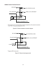
When the reset is released, instruction execution is started in the third machine cycle if the
reset signal is changed from “1” level to “0” level before the M1·S1 signal leading edge, and
in the fifth machine cycle if the reset signal is changed from “1” to “0” after the leading edge.
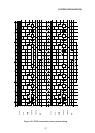
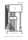
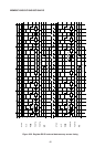
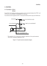
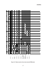
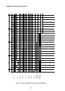
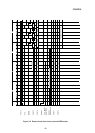
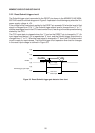
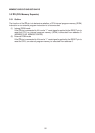
The reset circuit block diagram is shown in Figure 3-4, the reset start time charts in Figures
3-5 and 3-6, and the reset release time charts in Figures 3-7 and 3-8.
CPU RESET CONTROLIN
R=40KΩ
•
•
RESET
V
CC
+
–
Figure 3-4 MSM80C154S/MSM83C154S reset circuit block diagram