


MSM80C154S/83C154S/85C154HVS
38
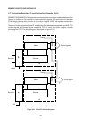
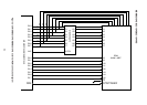
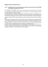
2.10.3 Procedures and circuit connections used when external data memory (RAM)
is accessed by registers R0 and R1
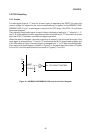
The MSM80C154S/MSM83C154S can be connected to an external 256 word ¥ 8-bit data
memory (RAM) when addressing the memory according to the contents of registers R0 and
R1 in the internal data memory (RAM).
The MOVX @Rr, A instruction is used when accumulator contents are transferred to an
external data memory, and the MOVX A, @Rr instruction is used when external data memory
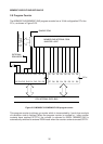
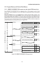
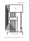
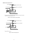
contents are transferred to the accumulator. The external data memory connection diagram
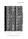
is shown in Figure 2-28 and the external data memory access time chart is shown in Figure
2-29.
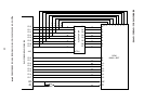
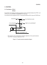
When the indirect register external memory instruction is executed, the CPU passes the R0
or R1 register contents to port 0, and the port 0 contents are latched externally by the ALE
signal. Data stored in the latch serves as the addresses 0 thru 7 of the external data memory.
The WR or RD external data memory control signal is subsequently generated by the CPU
to enable transfer of data between port 0 and the external data memory.
However, if the port 2 latched data is used in addresses 8 thru 15 of the external data memory,
the circuit connections are the same as when the data pointer (DPTR) is used, thereby
enabling a 64K byte ¥ 8-bit data memory to be accessed.