


1999 Apr 14 42
Philips Semiconductors Product specification
Audio processor with head amplifier for VHS hi-fi TDA9605H
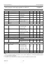
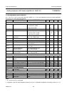
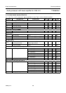
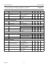
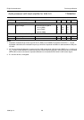
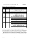
Table 41 Test modes for evaluation and measurement purposes
Notes
1. This test can be used with a HIGH-level input signal by setting bit HPD = 1; test input signal applied to pin HMSW.
2. Auto-normal is activated (bit AUTN = 1) during the test, i.e. the playback audio signal is not available.
3. The output level on pin ENVOUT shows 6 dB attenuation compared to the internal signal of the head amplifier output.
4. This test connects internal signal lines between the noise reduction and (de-)modulator circuit. The signals found
here are not compensated for temperature or tolerance spread and therefore level measurements are only relative.
Absolute values are not an indication of the overall performance. Typical audio level of the test inputs and outputs is
approximately −6.5 dBV for the standard −8 dBV line level and 50 kHz FM deviation.
5. The expander test requires the auto-normal function to be set inactive; i.e. an FM carrier signal should be available.
TEST HRL NIL3 NIL2 NIL1 NIL0 MODE DESCRIPTION
100001test 1 record mode; left channel FM carrier only (1.3 or 1.4 MHz)
100010test 2 record mode; right channel FM carrier only (1.7 or 1.8 MHz)
100011test 3 playback mode; left channel band-pass filter with HF AGC off;
EOS = 1 (test output on pin ENVOUT); notes 1 and 2
100100test 4 playback mode; right channel band-pass filter with HF AGC off;
EOS = 1 (test output on pin ENVOUT); notes 1 and 2
100101test 5 playback mode; HF AGC (left channel band-pass filter);
EOS = 1 (test output on pin ENVOUT); notes 1 and 2
100110test 6 playback mode; HF AGC (right channel band-pass filter);
EOS = 1 (test output on pin ENVOUT); notes 1 and 2
101000test 8 playback mode; head amplifier output signal;
EOS = 1 (test output on pin ENVOUT; notes 2 and 3
101010test 10 playback mode; HF envelope of right channel carrier;
EOS = 1 (test output on pin ENVOUT)
111001test 25 noise reduction and modem; note 4
test 25a left channel FM modulator (left carrier only);
record mode; volume setting = −3 dB; test input = line input left
test 25b left and right noise reduction (compressor);
record mode; output select function = mute;
test output = line output
test 25c left and right channel FM demodulator; playback mode;
output select function = mute; test output = line output
111010test 26 noise reduction and modem; note 4
test 26a right channel FM modulator (right carrier only);
record mode; volume setting = −3 dB; test input = line input right
test 26b left and right channel audio lowpass filter; record mode;
volume setting = −3 dB; output select function = mute;
test input = line input; test output = line output
test 26c left and right channel noise reduction (expander); playback mode;
volume setting = −3 dB; test input = line input; note 5