


1999 Apr 14 29
Philips Semiconductors Product specification
Audio processor with head amplifier for VHS hi-fi TDA9605H
7.9.3 TEST MODE
Several special tests can be selected for test, evaluation
and measurement purposes. The selection of these tests
is made by setting bit HRL and bits NIL3 to NIL0.
See Section 14.4 for an overview of the test modes.
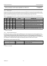
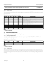
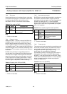
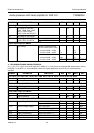
Table 30 Test mode (bit TEST)
Note
1. Power-on reset state.
7.9.4 P
OWER-ON RESET
Setting bit PORR = 1 ensures a reset of bit POR of the
read byte to logic 0. In this way, a reading of logic 1 for
bit POR always indicates the occurrence of an actual
I
2
C-bus register Power-on reset and can not be caused
accidentally by other I
2
C-bus control bits. Bit PORR has no
control function but it is an unused bit, dedicated by name
to change the I
2
C-bus register content from the Power-on
reset state.
Bit POR of the read byte is a logic AND function for
checking all I
2
C-bus register bits. Bit POR will read logic 1
when the I
2
C-bus register content equals the Power-on
reset default state and also when this state is set via the
I
2
C-bus control. Since a setting of bit PORR = 1 differs
from the Power-on reset default state, it forces a reset of
bit POR to logic 0 independent of other bit settings.
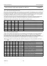
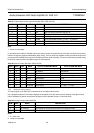
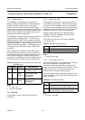
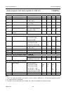
Table 31 Resetting of bit POR (bit PORR)
Note
1. Power-on reset state.
TEST MODE DESCRIPTION
0 operating
mode
standard operating; note 1
1 test mode test mode for special
measurements
PORR MODE DESCRIPTION
0 no reset note 1
1 bit POR
reset
reset of bit POR (read byte)
7.9.5 HEAD AMPLIFIER DISABLE
Bit HPD offers a special setting intended for use with some
of the built-in test modes and for support of particular
applications that do not require use of the integrated head
amplifier. By setting bit HPD = 1 the head amplifier
playback circuit is disabled. This mode enables direct input
signal to the HF AGC circuit via pin HMSW (AC coupled
via a 10 nF capacitor).
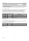
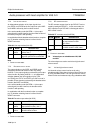
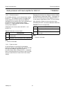
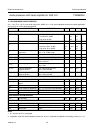
Table 32 Head amplifier playback disable (bit HPD)
Note
1. Power-on reset state.
7.9.6 P
OWER MUTING
The power mute function controls the mute switches on the
line and RF converter outputs. The power mute mode is
automatically activated via the Power-on reset function
during power-up of the supply voltage. During
power-down, the mute switches are activated
automatically by means of the auto-mute circuit which is
independent of the setting of bit MUTE. When setting
bit MUTE = 1 the output current on pins RFCOUT, LINEL,
LINER, DECL and DECR is limited to −1 mA for controlled
power-up response and the selected output signal is
muted (see Section 6.6).
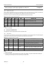
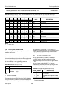
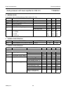
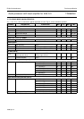
Table 33 Power mute (bit MUTE)
Note
1. Power-on reset state.
HPD MODE DESCRIPTION
0 operating
mode
standard operating mode; note 1
1 head
amplifier
disable
head amplifier disabled in playback
mode (for test or special
application)
MUTE MODE DESCRIPTION
0 no mute power muting released: mute
switches are open
1 mute power muting activated: mute
switches are closed; note 1