


1999 Apr 14 14
Philips Semiconductors Product specification
Audio processor with head amplifier for VHS hi-fi TDA9605H
During power muting the internal output signal is also
muted. After the output DC voltage has been established
power muting can be de-activated by setting bit MUTE = 0.
Now the mute switches are opened resulting in a
high-impedance path of 100 kΩ to ground. The output
current limiting is not active.
Power muting is also used in combination with the
integrated passive standby mode (bit STBP = 1). During
this mode the output circuits are switched off and the line,
decoder and RF converter output voltages decrease to 0 V
using a discharge current of 1 mA. Do not set power mute
mode and change the passive standby mode at the same
time. Power mute mode should be activated first, followed
by switching on or off of the passive standby mode to avoid
possible output glitches.
It should be noted that the time needed for stabilizing the
output DC voltage is proportional to the output capacitor
value. A safe mute time is 200 ms using a 10 µF capacitor
(t
mute
=C×20000 s). Power muting consumes
approximately 4 mA additional supply current, so to obtain
minimum power consumption the mute mode should be
de-activated after use. Very good performance is achieved
for power-up, power-down and passive standby mode
switching.
An auto-mute function is included which activates power
muting when the supply voltage drops below 7 V.
The performance of this auto-mute function depends upon
the power voltage drop rate. The voltage drop rate should
not exceed 1 V during 10 ms. The best performance
independent of voltage drop rate is realized by activating
the passive standby mode before switching off the power
supply voltage (by setting bit MUTE = 1 and bit STBP = 1).
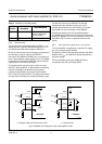
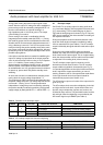
6.7 Envelope output
Pin ENVOUT is an analog output for stereo audio level
(e.g. level meter display) and for playback FM carrier level
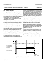
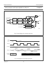
(e.g. auto-tracking). The functional diagram is given in
Fig.9 and the timing diagram is shown in Fig.10. Only one
ADC input is needed on the microcontroller for reading all
the required information.
During the playback mode the selection between audio
level and carrier level information is realized by setting
I
2
C-bus control bit EOS (see Table 3). The AF envelope
output is defined by the signal selection made at the output
select.
During the record mode bit EOS offers the selection
between the audio level of the output select or the audio
level of the fixed hi-fi stereo signal. This is a helpful setting
when the microcontroller uses the audio level information
to adjust the hi-fi recording level (volume control).
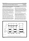
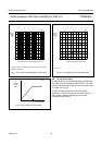
The HF envelope output signal is continuous and is
derived from the left channel carrier. The HF envelope
output exhibits a logarithmic characteristic (see Fig.11).
In a standard application circuit only the left channel carrier
level is required to support auto-tracking or manual
tracking. However, test 10 of the special test mode allows
for the right channel carrier level output instead for
measurement purposes (see Section 14.4).
The AF envelope output as a function of the output level is
given in Fig.12.
The AF envelope circuit uses time multiplexing for the left
and right channel audio level. A peak-hold function and
dynamic range compression (square root function) are
included for easy read out. The peak-hold function and the
left and right channel multiplexing are controlled by the
HID control signal on pin RMHID (see Table 4).
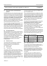
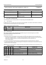
Table 3 Selection of the envelope output
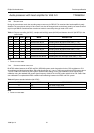
Table 4 AF envelope output with channel multiplexing
MODE BIT AFM BIT EOS ENVELOPE OUTPUT FUNCTION
Playback
0
0 AF envelope: via output select level meter display
1 HF envelope auto-tracking or manual tracking display
Record
1
0 AF envelope: via output select level meter display
1 AF envelope: hi-fi stereo record volume control (and level display)
HID SIGNAL LEVEL ON PIN RMHID AF ENVELOPE OUTPUT
LOW lower than 0.6 V or between 2.65 and 3.8 V left channel audio peak level
HIGH between 1.0 and 2.35 V or higher than 4.3 V right channel audio peak level