


1999 Apr 14 10
Philips Semiconductors Product specification
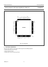
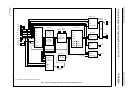
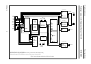
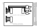
Audio processor with head amplifier for VHS hi-fi TDA9605H
6.1 Record-mute mode or head identification
selection
Pin RMHID allows input of two independent digital control
signals for selecting the record-mute or head identification
modes which are voltage coded. The RM control signal is
selected via a 10 kΩ resistor and the HID control signal is
selected via a 18 kΩ resistor. This set-up enables the two
signals within the TDA9605H to be separated. The RM
control signal is only in use during the record mode
(bit AFM = 1); during the playback mode (bit AFM = 0) the
RM signal is ignored. Pin RMHID should be connected to
ground when the RM control signal is not used.
The use of the RM control signal is optional since the same
function is available via the I
2
C-bus control in the
record-mute mode. However, accurate timing of recording
start and stop may sometimes be difficult to realize via the
I
2
C-bus control. In this event the RM control signal can be
used instead. There is also the possibility to use the
record-mute mode control line of the video head amplifier.
6.2 Hi-fi audio output level
When the application circuit is used in accordance with the
application diagram, the standard FM deviation of 50 kHz
equals a 1 kHz audio signal of −8 dBV line output level
(bit LOH = 0). A different standard audio level can be
selected by changing the external filter components of the
noise reduction on pins EMPHL and EMPHR
(see Section 14.3). The standard audio level changes
proportionally to the impedance of the external
de-emphasis filter.
6.3 Reference current
The external resistor connected to pin I
ref
defines the
internal reference currents and determines the
temperature stability of circuits adjusted by the
auto-calibration function.
6.4 Head amplifier
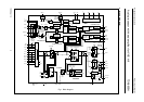
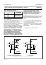
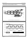
6.4.1 PLAYBACK MODE
The playback mode is selected by setting bit AFM = 0.
During the playback mode the input circuit on pins PBIN2
and PBIN1 is enabled (see Fig.6). Pin RECOUT is
disabled and pin HMSW shows a low impedance to
ground, so realizing an AC ground for the head circuit via
the external capacitor connected between these pins.
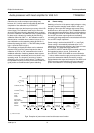
The head identification (HID) signal on pin RMHID selects
between the head signals on pins PBIN2 or PBIN1. Head
selection is defined as shown in Table 1.
The state of the RM control signal on pin RMHID is don’t
care in the playback mode.
I
2
C-bus control bits HAC2, HAC1 and HAC0 offer a wide
selection of playback amplification to fit different head and
head transformer specifications. The advised setting of the
playback amplification realizes a level of 24 mV (RMS) for
each carrier signal after the head amplifier to obtain a
17 dB overhead compared to the auto-normal level (hi-fi
detection). However, performance is not critical and a
different setting can be used if desired.
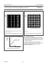
The carrier level can be measured using the HF envelope
output voltage on pin ENVOUT (bit EOS = 1). During
standard operating mode the HF envelope signal is
derived from the left channel carrier amplitude
(1.3 or 1.4 MHz carrier) but the special test 10 of the test
mode also enables the HF envelope output of the right
channel carrier amplitude (1.7 or 1.8 MHz carrier).
The advised carrier playback level of 24 mV (RMS) equals
an HF envelope voltage of 3.3 V.
The head amplifier output signal can be monitored directly
by using test 8 of the test mode. Pin ENVOUT functions as
the test output showing 6 dB attenuation compared to the
actual head amplifier output level (see Section 14.4).
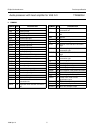
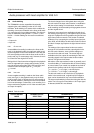
Table 1 Selection of the head signal
6.4.2 R
ECORD-MUTE MODE
The record-mute mode is selected by setting bit AFM = 1
and either setting bits DOC, SHH and DETH to logic 0 or
switching the RM control signal to HIGH-level.
During the record-mute mode no recording current is
present on pin RECOUT (see Fig.6). The head amplifier
status actually equals the playback mode, however, the
second amplifier stage is disabled to minimize power
consumption.
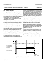
The RM control signal on pin RMHID enables fast
switching between the record and record-mute modes
(see Table 2). If the I
2
C-bus control is set to the record
mode, the use of record-mute mode control via pin RM
allows for accurate timing of recording start and stop,
independent of the I
2
C-bus control (see Section 6.1).
HID
SIGNAL
LEVEL ON PIN RMHID
SELECTION OF
HEAD SIGNAL
LOW lower than 0.6 V or
between 2.65 and 3.8 V
pin PBIN2
(head 2)
HIGH between 1.0 and 2.35 V
or higher than 4.3 V
pin PBIN1
(head 1)