


1999 Apr 14 12
Philips Semiconductors Product specification
Audio processor with head amplifier for VHS hi-fi TDA9605H
6.5 Automatic calibration
The integrated auto-calibration system is activated by
means of bit CALS of the power byte (see Fig.7).
The auto-calibration system ensures hi-fi processing is
well in accordance with the VHS hi-fi system standard by
an automated adjustment of carrier frequencies,
band-pass filters and noise reduction filters. Calibration is
only needed after start-up of the video recorder.
The calibration settings remain stable as long as the
supply voltage (V
CC
) is present.
Auto-calibration is only executed in the record-mute mode
or record mode and no standby mode or test mode should
be selected, i.e. auto-calibration requires the setting of
bit AFM = 1, bit STBP = 0, bit STBA = 0 and bit TEST = 0.
Auto-calibration is started after setting bit CALS = 1.
Calibration is performed fully automatically, using the HID
control signal as a time reference. Audio signals are not
disturbed during the calibration process.
Calibration of the oscillator frequencies is performed by
measuring the number of oscillator cycles within one
period when the HID control signal is at HIGH-level and
comparing this result with an internal value stored in the
Read Only Memory (ROM). Four different ROM values are
available for NTSC or PAL (SECAM) system calibration of
both the left and right channel carrier.
In case of NTSC a special routine is active for the
calibration of the right channel carrier which results in a
frequency difference between the left and right channel
carrier near to 401.2 kHz. This value effectively reduces
the crosstalk from hi-fi carriers to video colour signal as
present during Extended Play (EP) tape speed. NTSC
calibration uses a standard HID control signal of 29.97 Hz
(pulse width =16.683 ms) where PAL calibration uses a
standard HID control signal of 25 Hz (pulse
width = 20 ms). After auto-calibration the maximum
frequency error is ±5 kHz assuming a time error of
maximum of 5 µs when the HID control signal is at
HIGH-level. Jitter on the HID control signal should not
exceed 1 µs to realize EP optimization within ±2 kHz for
NTSC. In general, the crystal based HID control signal
available in the video recorder can be used without
modification.
When the calibration of the oscillators is completed the
band-pass filters are calibrated. The integrated weighting
and FM de-emphasis filters of the noise reduction are
calibrated at the same time.
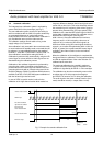
The total auto-calibration time needed is maximum
17 cycles of the HID control signal. Completion of the
calibration is signalled by bit CALR =1 of the read byte.
The calibration can also be monitored by means of the
envelope output. For this purpose the voltage on
pin ENVOUT is forced to >2.5 V during the calibration.
The audio signal to the audio envelope function (level
meter) should be muted (i.e. output select = mute).
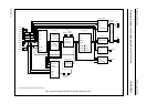
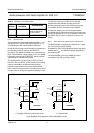
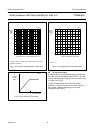
Fig.7 Example of automatic calibration flow.
handbook, full pagewidth
MGR842
logic 1
logic 0
logic 1
logic 0
4 V3 V
5 V
calibration
ready
I
2
C-bus write bit CALS
I
2
C-bus read bit CALR
ENVOUT output
RMHD input
left channel oscillator
right channel oscillator
band-pass and
noise reduction filters