


1999 Apr 14 2
Philips Semiconductors Product specification
Audio processor with head amplifier for VHS hi-fi TDA9605H
CONTENTS
1 FEATURES
2 GENERAL DESCRIPTION
3 ORDERING INFORMATION
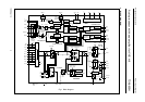
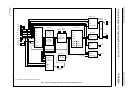
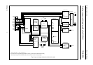
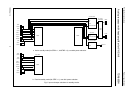
4 BLOCK DIAGRAM
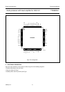
5 PINNING
6 FUNCTIONAL DESCRIPTION
6.1 Record-mute mode or head identification
selection
6.2 Hi-fi audio output level
6.3 Reference current
6.4 Head amplifier
6.4.1 Playback mode
6.4.2 Record-mute mode
6.4.3 Record mode
6.4.4 Head amplifier power supply and ground
6.5 Automatic calibration
6.6 Power muting
6.7 Envelope output
6.8 RF converter output
6.9 Audio dubbing
6.9.1 Output mix
6.9.2 Input mix
7I
2
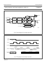
C-BUS PROTOCOL
7.1 Addresses and data bytes
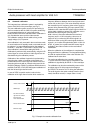
7.2 Valid transmissions to and from the TDA9605H
7.3 Overview of the TDA9605H I
2
C-bus control
7.4 Control byte at subaddress 00H
7.4.1 Audio FM mode
7.4.2 Playback mode
7.4.3 Record mode
7.4.4 System standard selection
7.4.5 Head amplifier playback amplification
7.4.6 Head amplifier record current
7.5 Select byte at subaddress 01H
7.5.1 Decoder output select
7.5.2 Head amplifier record current range select
7.5.3 Normal input level
7.6 Input byte at subaddress 02H
7.6.1 Input select
7.6.2 Normal select
7.7 Output byte at subaddress 03H
7.7.1 Line output amplification
7.7.2 Output select
7.7.3 Envelope output select
7.7.4 Line output select
7.7.5 Decoder output select
7.7.6 RF converter mute
7.8 Volume bytes at subaddresses 04H, 05H
and 06H
7.8.1 Left and right volume control
7.9 Power byte at subaddress 07H
7.9.1 Calibration start
7.9.2 DC output voltage selection
7.9.3 Test mode
7.9.4 Power-on reset
7.9.5 Head amplifier disable
7.9.6 Power muting
7.9.7 Standby select
7.10 Read byte
7.10.1 Calibration ready
7.10.2 Auto-normal selection
7.10.3 Calibration error
7.10.4 Power-on reset
8 LIMITING VALUES
9 THERMAL CHARACTERISTICS
10 GENERAL CHARACTERISTICS
11 RECORD-MUTE MODE CHARACTERISTICS
12 RECORD MODE CHARACTERISTICS
13 PLAYBACK MODE CHARACTERISTICS
14 APPLICATION AND TEST INFORMATION
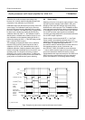
14.1 RM and HID control signals
14.2 Reference current resistor
14.3 Setting line output level
14.4 Test modes
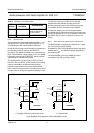
15 INTERNAL CIRCUITRY
16 PACKAGE OUTLINE
17 SOLDERING
17.1 Introduction to soldering surface mount
packages
17.2 Reflow soldering
17.3 Wave soldering
17.4 Manual soldering
17.5 Suitability of surface mount IC packages for
wave and reflow soldering methods
18 DEFINITIONS
19 LIFE SUPPORT APPLICATIONS
20 PURCHASE OF PHILIPS I
2
C COMPONENTS