


1999 Apr 14 27
Philips Semiconductors Product specification
Audio processor with head amplifier for VHS hi-fi TDA9605H
7.7.4 LINE OUTPUT SELECT
An independent selection of the input signals from
pins EXT2L and EXT2R to the line outputs on pins LINEL
and LINER is offered by the line select function.
In the active standby mode (bit STBA = 1) the output
select signal is muted. However, the line select function of
the ext2 input signal is still operating.
In combination with the decoder select function a complete
pay-TV decoder switching feature is offered via the
SCART connector.
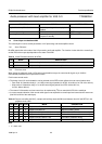
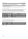
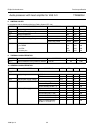
Table 24 Line output select (bit LOS)
Note
1. Power-on reset state.
7.7.5 D
ECODER OUTPUT SELECT
The output signals on pins DECL and DECR can be
selected by the decoder select function. By setting
bit DOS = 0, the output signals are selected by the output
select function. By setting bit DOS = 1, an independent
selection between the input signals on pins TUNL
and TUNR, pins EXT1L and EXT1R, pin SAP or mute is
possible. These signals are selected by the decoder select
function (bits DOS1 and DOS2).
In the active standby mode (bit STBA = 1) the output
select signal is muted. However, the decoder select
function is still operating.
In combination with the line select function a complete
pay-TV decoder switching feature is offered via the
SCART connector.
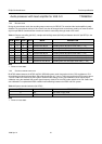
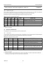
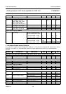
Table 25 Decoder output select (bit DOS)
Note
1. Power-on reset state.
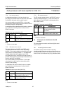
LOS MODE DESCRIPTION
0 output
select
line output signal is set by output
select; note 1
1 ext2 line output signal is from input
signal on pins EXT2L and EXT2R
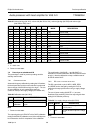
DOS MODE DESCRIPTION
0 output
select
decoder output signal is set by the
output select function; note 1
1 decoder
select
decoder output signal is set by the
decoder select function
7.7.6 RF CONVERTER MUTE
The RF converter output signal on pin RFCOUT can be
muted by setting bit RFCM = 1. In this mute mode, the
AGC capacitor on pin RFCAGC is discharged and the
AGC control is reset.
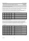
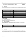
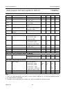
Table 26 RF converter mute (bit RFCM)
Note
1. Power-on reset state.
7.8 Volume bytes at subaddresses 04H, 05H
and 06H
The volume bytes are used to set left and right channel
volume control.
7.8.1 Left and right volume control
Left channel volume control can be set by using
subaddress 04H. Right channel volume control can be set
by using subaddress 05H. Left and right channel volume
control can be set simultaneous by using subaddress 06H.
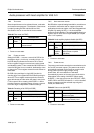
RFCM MODE DESCRIPTION
0 AGC RF converter output signal is set by
the output select function:
AGC active
1 mute RF converter output signal is muted
and AGC control is reset; note 1