


1999 Apr 14 30
Philips Semiconductors Product specification
Audio processor with head amplifier for VHS hi-fi TDA9605H
7.9.7 STANDBY SELECT
The TDA9605H is switched in the low-power active
standby mode by setting bit STBA = 1. Most circuits are
switched inactive for reducing power consumption.
However, the RF converter, line and decoder outputs
remain active in this mode and the direct audio selections
offered via the line select function and the decoder select
function remain available. The selected output signal is
muted during the active standby mode.
The TDA9605H is switched in the minimum power passive
standby mode by setting bit STBP = 1. All circuits are
switched inactive to obtain minimum power consumption
except for the power mute circuit, the I
2
C-bus and the line
input reference buffer (i.e. the DC voltage on pins 1 to 11
remains active). When bit STBP = 1 a discharge current of
1 mA is active on pins RFCOUT, LINEL, LINER, DECL
and DECR.
Power muting ensures disturbance-free switching of the
line and RF converter outputs to and from the passive
standby mode. In the passive standby mode power muting
can be de-activated again to achieve minimum power
consumption. The calibration and I
2
C-bus registers are not
affected in the active standby or passive standby mode.
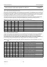
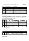
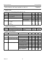
Table 34 Standby passive (bit STBP) and standby active
(bit STBA); note 1
Notes
1. X = don’t care.
2. Power-on reset state.
7.10 Read byte
The read byte is used for reading the device state
information.
STBP STBA MODE DESCRIPTION
0 0 operating standard operating mode:
full function; note 2
0 1 active
standby
active standby mode:
reduced power
consumption
1 X passive
standby
passive standby mode:
minimum power
consumption
7.10.1 CALIBRATION READY
The completion of calibration is signalled by changing
bit CALR from logic 0 to logic 1. Bit CALR remains logic 0
if for some reason a calibration can not be completed (i.e.
no HID control signal available or the hi-fi processing is in
the playback mode). Bit CALR will also return to logic 0 if
calibration is lost due to a Power-on reset situation.
Additional information about the calibration result is
available via bit CALE. Calibration is found correct if
bit CALR = 1 and bit CALE = 0.
Pin ENVOUT can also be used to monitor calibration
(see Section 6.5).
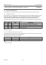
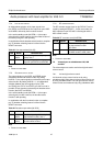
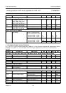
Table 35 Calibration ready (bit CALR)
Note
1. Power-on reset state.
7.10.2 A
UTO-NORMAL SELECTION
The auto-normal function is activated when no hi-fi carrier
input signal is detected in the playback mode.
The auto-normal function overrules the settings of the
output select function and selects normal sound (i.e. linear
audio) instead of hi-fi. The state of the auto-normal
function can be checked by reading bit AUTN.
The auto-normal function and therefore bit AUTN is only
valid in the playback mode. Bit AUTN is always logic 0 in
the record mode.
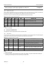
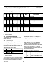
Table 36 Auto-normal (bit AUTN)
Note
1. Power-on reset state.
CALR DESCRIPTION
0 not calibrated; note 1
1 auto-calibration completed
AUTN DESCRIPTION
0 hi-fi carrier available; audio FM signal is
detected from tape in playback mode; note 1
1 normal sound selected instead of hi-fi carrier;
no audio FM signal is detected from tape