


1999 Apr 14 23
Philips Semiconductors Product specification
Audio processor with head amplifier for VHS hi-fi TDA9605H
7.5 Select byte at subaddress 01H
The select byte is used for decoder output select, record current range select and linear audio volume control.
7.5.1 D
ECODER OUTPUT SELECT
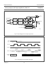
By setting bit DOS = 0 of the output byte, the decoder output signal on pins DECL and DECR is defined by the output
select function. However, by setting bit DOS = 1 the decoder select function enables several independent signal
selections controlled via bits DOS1 and DOS0. Via the decoder select function the input signals on pins TUNL
and TUNR, pins EXT1L and EXT1R and pin SAP can be selected. The mute mode can also be selected.
The indicated decoder select function modes are also available during the active standby mode by setting bit STBA = 1.
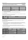
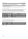
Table 15 Decoder output select (bits DOS1 and DOS0)
Note
1. Power-on reset state.
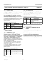
7.5.2 H
EAD AMPLIFIER RECORD CURRENT RANGE SELECT
The default selection of eight recording currents set by bits HAC2, HAC1 and HAC0 of the control byte is extended with
four additional low level recording currents by setting bit HRL = 1.
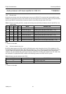
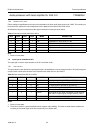
Table 16 Head amplifier record low current (bit HRL)
Note
1. Power-on reset state.
DOS1 DOS0 MODE DESCRIPTION
0 0 tuner selection of input signal on pins TUNL and TUNR; note 1
0 1 ext1 selection of input signal on pins EXT1L and EXT1R
1 0 SAP selection of input signal on pin SAP
1 1 mute muting the input signal
HRL MODE DESCRIPTION
0 high current selection of 8 medium and high-level recording currents; note 1
1 low current selection of 4 low-level recording currents