


1999 Apr 14 13
Philips Semiconductors Product specification
Audio processor with head amplifier for VHS hi-fi TDA9605H
Otherwise, the audio envelope output voltage may
become >2.5 V which makes it impossible to detect the
completion of the calibration on pin ENVOUT.
Calibration relies upon the frequency accuracy of the HID
control signal. The calibration result may be incorrect
when the HID control signal is disturbed during a critical
part of the calibration. An additional check is incorporated
to detect such a situation by reading bit CALE during
calibration. When bit CALE = 1, the calibration result is
detected to be unreliable due to external causes. A new
auto-calibration can be started by setting bit CALS = 0
followed by setting bit CALS = 1. Bit CALE always reads
logic 1 when bit CALS is logic 0.
The oscillators and band-pass filters can be switched
between NTSC and PAL system frequencies after a
calibration in NTSC or PAL mode without the need of
additional calibration. Switching between these system
modes is executed immediately and can be done in any
operating mode. The frequency accuracy of system
switching is 100 ±3 kHz for both carriers. To obtain the
best possible frequency accuracy in the record mode it is
good practice to recalibrate after system switching.
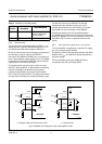
6.6 Power muting
Switching off and on of the power supply voltage or using
the built-in passive standby mode results in rising and
dropping of the output DC voltages and causes strong
disturbances on the output pins. The TDA9605H includes
three integrated mute switches to block such disturbances
so avoiding the need for an external mute circuit. Pop-free
line and RF converter output signals are realized by
connecting the integrated power mute switches behind the
line and RFC output capacitors.
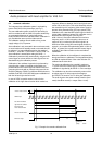
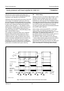
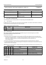
Power muting is active when bit MUTE = 1 (see Fig.8).
Power muting is automatically activated when V
CC
is
switched on, because this situation is the Power-on reset
default state. The integrated mute switches on
pins MUTEC, MUTEL and MUTER are closed and form a
low-impedance path to ground. Furthermore, the
pins RFCOUT, LINEL and LINER are current limited to
−1 mA to avoid excessive supply currents and to achieve
good noise attenuation without the need for a series
resistor between the output and mute pins. Pins DECL and
DECR are also current limited for using the integrated
power mute switches or for assisting external muting.
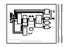
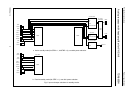
Fig.8 Examples of power mute control and the auto-mute function.
handbook, full pagewidth
MGR843
V
CC
auto-mute
(V
CC
< 7 V)
bit MUTE (I
2
C-bus)
(
1)
(
1)
bit STBP (I
2
C-bus)
MUTEC
MUTEL
MUTER
RFCOUT
LINEL
LINER
output signal
with power mute
t
mute
t
mute
t
mute
t
mute
t
mute
auto-mute
active
operation
power
off
power
off
active
operation
power off
(standby)
active
operation
passive
standby
(1) Power-on reset.