


Masterpage:Right-Full-NoTitle0
EN
57
Filename [DVS3U_3-EN.fm]
Page 57 January 11, 2002 2:16 pm
1
32
1
32
1
32
B
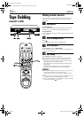
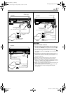
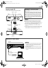
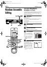
If the camcorder has an S-VIDEO output connector...
Camcorder
AUDIO input
Player
VIDEO input
EDIT
Audio/Video cable
(supplied)
Mini-plug cable
(not supplied)
(JVC camcorder only)
PAUSE
connector
Recorder
Audio/video cable
(supplied)
AUDIO OUT
Camcorder
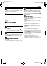
S-VIDEO input
Player
AUDIO
input
S-VIDEO OUT
S-Video cable
(supplied)
Mini-plug cable
(not supplied)
(JVC camcorder only)
PAUSE
connector
Recorder
To AUDIO/VIDEO
OUT connector
A
If the camcorder has no S-VIDEO output connector...
EDIT
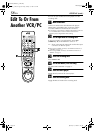
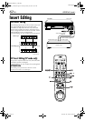
C
If the camcorder has a DV IN/OUT connector ...
Camcorder
Player
Mini-plug cable
(not supplied)
(JVC camcorder only)
PAUSE
connector
Recorder
EDIT
DV IN/OUT
DV cable (VC-VDV204)
(not supplied)
DV IN/
OUT
NOTES:
About DV IN/OUT connector
● To output digital signal when dubbing from the VHS deck to
other device through the DV IN/OUT connector, press ,
and then press PLAY (
4
) to start playback on the VHS deck.
● To input digital signal when dubbing from other device to
the VHS deck through the DV IN/OUT connector, press
then S-VHS, and then press REC (
7
) to start recording on the
VHS deck.
● It is possible to control the DV deck from the AVC protocol-
equipped device that is connected to the DV IN/OUT
connector. To control the VHS deck, use the buttons on this
VCR and the Remote.
●
Dubbing is also possible using the rear panel connectors.
●
All necessary cables can be obtained from your dealer.
●
When you select “EDIT” to dub tapes in step
4
, be sure to select
“AUTO” (or “NORM” when “VIDEO CALIBRATION” is set to
“OFF”) after you finish dubbing the tapes.
●
When you are editing through the DV IN/OUT connector, the
VCR will stop if the signal is interrupted.
●
When connecting this VCR to a device equipped with a DV
input connector, be sure to use the optional DV cable
(VC-VDV204).
Yellow:
not connected
DVS3U_3-EN.fm Page 57 Friday, January 11, 2002 2:17 PM