


Specifying Share Timeout and String
ida FS 250, Operator's Guide
-22-
4. Operation of ida FS 250
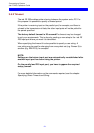
The ida FS 250 top panel has been designed to register the operation of the
box via the four following indicator LEDs :
• CU (contact to control unit)
• PAR (parallel input)
• SER (serial input)
• READY (printer)
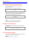
4.1 ida FS 250 top panel
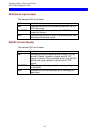
CU
The CU indicator has 3 states which signal the following:
State Indication
ON
Contact with the control unit.
BLINKING
In test mode.
OFF
No contact of the control unit, or the contact
has been broken for more than 1 minute.
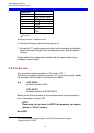
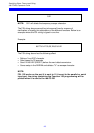
PAR (Parallel input)
The indicator LED has 2 states:
State Indication
ON
Indicates that the box is processing data from the
Centronics parallel port
OFF
Indicates that the box is idle or processing data from
the twinax/RS232 inputs