


Connecting to System
ida FS 250, Operator's Guide
-12-
3. Installation and Connections of the
ida FS 250
This chapter starts with an overview of the functionality of the rear panel.
Then follows a description of how you connect the ida FS 250 box to a
printer and finally you will find instructions for connection to a system.
NOTE:
Before you start the installation, make sure that you set the address
switch and the desired emulation. See the description in the section:
Emulation.
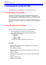
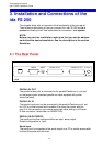
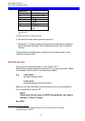
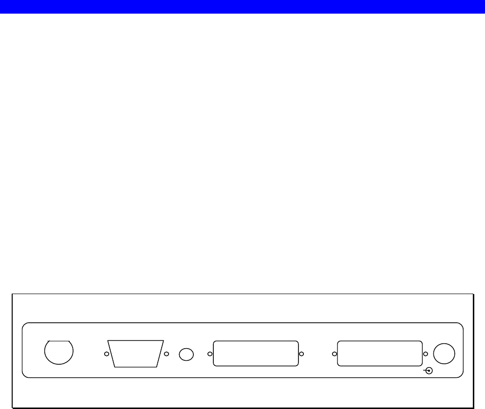
3.1 The Rear Panel
RS232
12-18 VDC.
0.7A
PARALLEL IN PARALLEL OUTADDR
+ --
B
A
T
6
5
4
3
2
0
1
A = PCL
Fig 2-1 ida FS 250 Rear Panel
PARALLEL OUT
The parallel output port is connected to the parallel/Centronics in put port
on the target printer (standard parallel out cable supplied with printer
should be used).
PARALLEL IN
The parallel input port can be connected to the parallel/Centronics out put
on a PC or similar source which enables it to share the printer with the
host. For this connection you need a spare part cable ending in a 25-pole
D-Sub connector (i-data order no. 999022 030).
SERIAL (IN/OUT) RS232
The serial port can be configured either as input or as output.
Default configuration is input.
Serial input
The serial port is connected to the serial output on a PC or similar source able
to share the printer with the host.